Clean room fluid energy distribution control system

A control system and energy distribution technology, applied in the general control system, control/regulation system, gas/liquid distribution and storage, etc., can solve the problems of low measurement accuracy, cleaning blind spots, incomplete cleaning, etc., and reach the heating area Larger, fewer pipe connections, less risk of contamination

Pending Publication Date: 2022-05-13
四川科特空调净化有限责任公司
View PDF0 Cites 0 Cited by
  • Summary
  • Abstract
  • Description
  • Claims
  • Application Information

AI Technical Summary

Problems solved by technology

[0009] The existing clean room fluid energy distribution system mainly has incomplete cleaning and cleaning blind areas, the measurement accuracy is not high, and the preparation and delivery are in different areas, resulting in cross flow of personnel

Method used


Image

  • Clean room fluid energy distribution control system
  • Clean room fluid energy distribution control system
  • Clean room fluid energy distribution control system

Examples


Embodiment Construction

[0029] In order to make the purpose, technical solution and advantages of the present application clearer, the present application will be further described in detail below in conjunction with the accompanying drawings and embodiments. It should be understood that the specific embodiments described here are only used to explain the present application, and are not intended to limit the present application.

[0030] On the contrary, this application covers any alternatives, modifications, equivalent methods and schemes within the spirit and scope of this application as defined by the claims. Further, in order to make the public have a better understanding of the application, some specific details are described in detail in the detailed description of the application below. The present application can be fully understood by those skilled in the art without the description of these detailed parts.

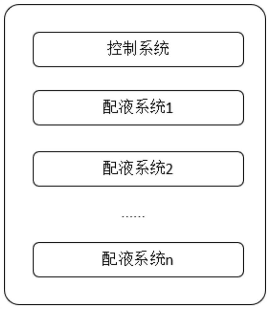
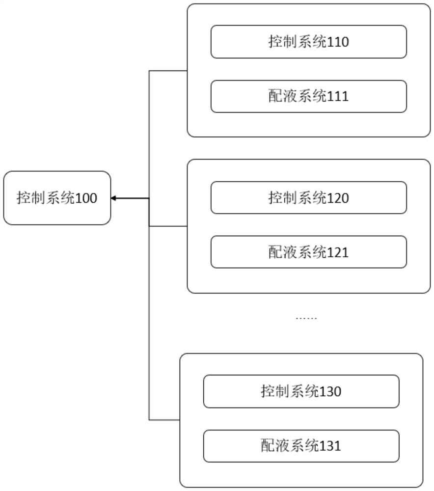
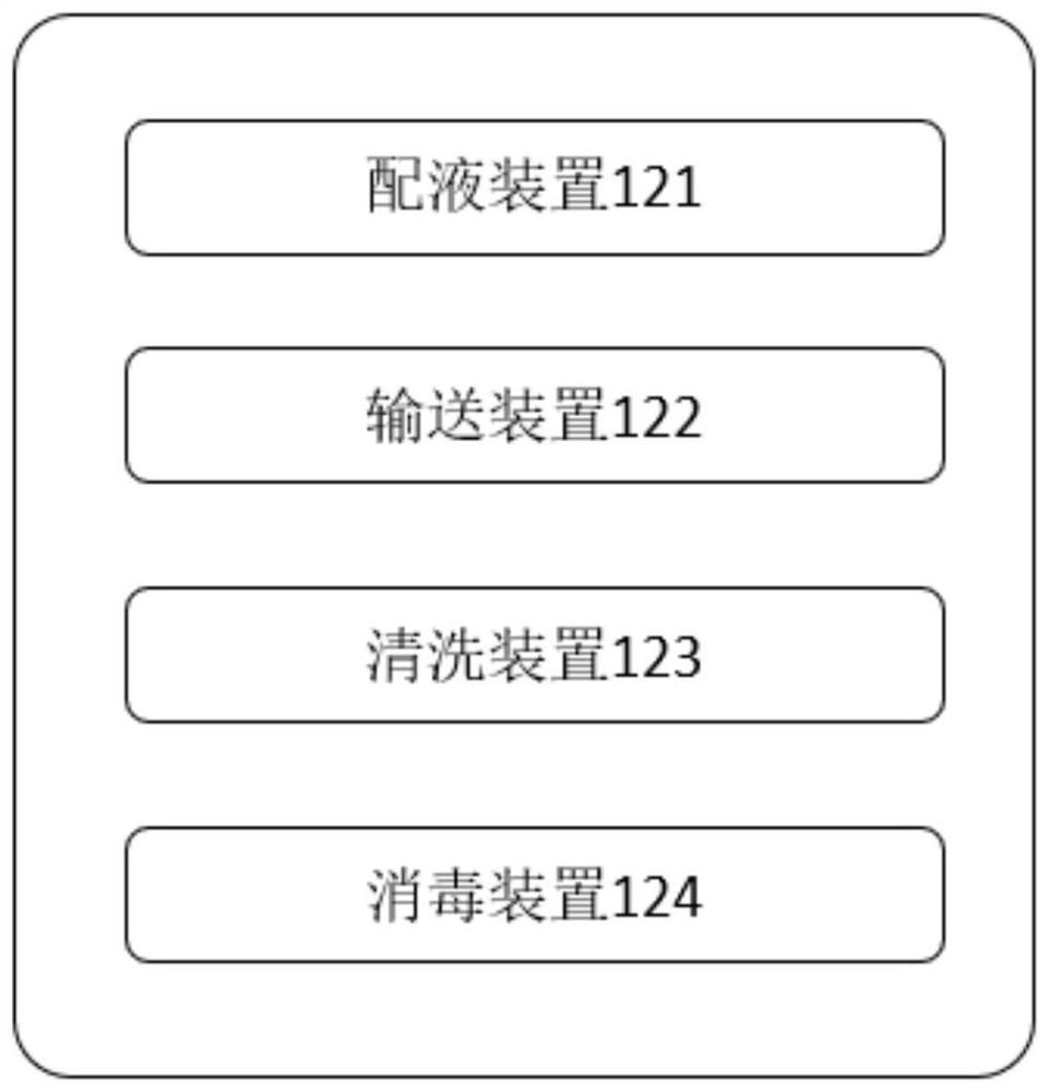
[0031] The following will combine Figure 1-3 A clean room fluid energy distrib...


PUM


Abstract

The invention provides a clean room fluid energy distribution control system, which comprises a control system and a plurality of liquid preparation systems, and the control system is in communication connection with the plurality of liquid preparation systems; each liquid preparation system in the plurality of liquid preparation systems comprises a liquid preparation device, a conveying device, a cleaning device and a disinfection device; the conveying device, the cleaning device and the sterilizing device are respectively arranged on the liquid preparation device.

Description

technical field [0001] The invention relates to the technical field of energy control, in particular to a clean room fluid energy distribution control system. Background technique [0002] A clean room refers to a space where the air cleanliness reaches a specified level and can be used for human activities. Its function is to control particulate (dust particle) contamination. To meet the production and scientific experiment activities of precision products. The clean room is by no means limited to "clean". Different industries and departments have considerable requirements for temperature, temperature, lighting, noise, static electricity, and micro-vibration. Decoration), purification air conditioning, pure water, pure gas, power electricity, lighting electricity, process piping and other professional technologies in one product. [0003] In order to meet the new version of the "GMP" standard, the production automation of the pharmaceutical industry has been more and mor...

Claims


Application Information

Patent Timeline
Patent Type & Authority Applications(China)
IPC IPC(8): G05B19/05B01F35/10B01F35/213F17D1/08F17D3/01F24F3/167
CPCG05B19/054F24F3/167F17D1/08F17D3/01G05B2219/1103
Inventor 崔静涛冯泽旭蔡皓
Owner 四川科特空调净化有限责任公司
Why Eureka
Try Eureka