Device and method for testing axial dynamic rigidity of built-in machine tool spindles

A technology of machine tool spindle and testing device, which is applied in mechanical bearing testing, measuring device, testing of machine/structural components, etc., can solve the problems of difficult testing of spindle dynamic characteristics and difficult testing of machine tool spindle dynamic characteristics.

Active Publication Date: 2017-05-31
HEBEI UNIV OF TECH
View PDF10 Cites 5 Cited by
  • Summary
  • Abstract
  • Description
  • Claims
  • Application Information

AI Technical Summary

Problems solved by technology

The test device uses the force sensor and displacement sensor built in the main shaft to measure the axial force and deformation of the machine tool under the actual cutting state in real time, and the axial dynamic stiffness of the main shaft is calculated by the data processing part, which solves the problem of the dynamic characteristics of the machine tool main shaft. Problems that are difficult to test in the actual cutting state, and provide a basis for future spindle intelligent perception, intelligent detection, intelligent adjustment of control parameters, and parameter optimization
The test method is simple, reliable, and easy to operate. It does not require the operation of special driving, transmission, control and other units. Testing of the dynamic stiffness of the lower spindle

Method used


Image

  • Device and method for testing axial dynamic rigidity of built-in machine tool spindles
  • Device and method for testing axial dynamic rigidity of built-in machine tool spindles
  • Device and method for testing axial dynamic rigidity of built-in machine tool spindles

Examples


Embodiment Construction

[0030]The present invention will be further described below in conjunction with the embodiments and accompanying drawings, but this should not be used as a limitation to the protection scope of the claims of the present application.

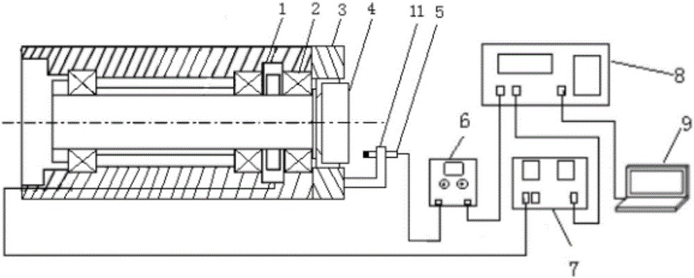
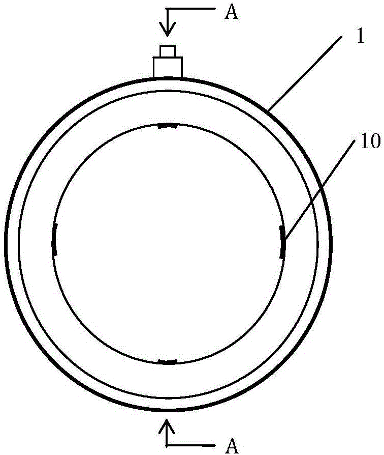
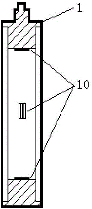
[0031] Built-in machine tool spindle axial dynamic stiffness testing device of the present invention (abbreviation device, see Figure 1-6 ) includes a force sensor sleeve 1, an axial displacement sensor 5, a front end device 6, a charge amplifier 7, a data acquisition card 8, a data processing terminal 9, a force sensor 10 and a magnetic base 11; the force sensor sleeve 1 is set on On the main shaft 4, and between the two bearings 2 at the front and middle of the main shaft, the force sensor sleeve 1 is in the shape of a ring, and on the inner side of the ring, there are four strain gauges 10 evenly distributed along the circumferential direction, corresponding to The force types of the two adjacent strain gauges are opposite, that is, one strai...


PUM


Abstract

The invention relates to a device and a method for testing the axial dynamic rigidity of built-in machine tool spindles. The device is characterized by comprising a force sensor sleeve, an axial displacement sensor, a front end machine, a charge amplifier, a data acquisition card, a data processing end, a force sensor and a magnetic base; the force sensor sleeve sleeves a spindle, is positioned between two bearings at the upper front and in the middle of the spindle and is in the shape of a circular ring, four strain gauges are circumferentially uniformly distributed on the inner side surface of the circular ring, stress types of every two adjacent strain gauges are opposite to each other, in other words, one of every two adjacent strain gauges is horizontally arranged, and the adjacent strain gauge is vertically arranged; the four strain gauges are connected with one another according to full-bridge circuit modes to form the force sensor, an output end of a full-bridge circuit is led out from a side surface of the force sensor sleeve and is connected with an input end of the charge amplifier by a signal wire, the charge amplifier is arranged on a worktable, and an output end of the charge amplifier is connected with the data acquisition card.

Description

technical field [0001] The invention belongs to the field of mechanical vibration and testing, in particular to a built-in machine tool spindle axial dynamic stiffness testing device and testing method. The device and the method are used for testing the axial dynamic rigidity of the main shaft in the actual cutting state of the CNC machine tool. Background technique [0002] The dynamic performance of the machine tool reflects the ability of the machine tool to resist dynamic external loads. It is closely related to the load capacity and vibration resistance, and directly affects the machining accuracy of the machine tool and the machining quality of the parts. Among them, the dynamic stiffness is an important index to measure the dynamic performance of the machine tool. The dynamic stiffness of the machine tool refers to the stiffness exhibited by the machine tool under the action of a sinusoidal alternating load changing at a certain frequency, which characterizes the abil...

Claims


Application Information

Patent Timeline
Patent Type & Authority Applications(China)
IPC IPC(8): G01M5/00G01M13/04
CPCG01M5/0058G01M13/04Y02P90/02
Inventor 杨泽青李增强刘丽冰张艳蕊朱金达朱志辉李莉张俊峰彭凯谭飏陈英姝杨伟东韩靖范敏张炳寅
Owner HEBEI UNIV OF TECH
Why Eureka
Try Eureka