Outdoor unit of air conditioner
A technology for air conditioners and outdoor units, applied in the field of outdoor units, can solve problems such as frame deformation, achieve the effects of preventing frame deformation, reducing the number of assembly steps, and preventing vibration noise
- Summary
- Abstract
- Description
- Claims
- Application Information
AI Technical Summary
Problems solved by technology
Method used
Image

Examples
no. 1 approach
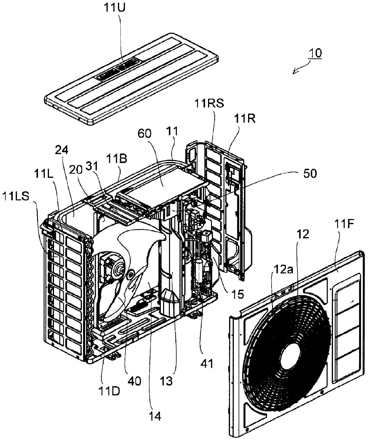
[0035] Embodiments of the present invention will be described below with reference to the drawings. figure 1 It is an exploded perspective view of the outdoor unit 10 . The outdoor unit 10 includes a rectangular parallelepiped casing 11 , an upper panel 11U is disposed on the upper portion of the casing 11 , and a bottom panel 11D is disposed on the bottom of the casing 11 . In addition, on the peripheral surface of the housing 11, a front panel 11F is arranged on the front side, and a rear panel 11B is arranged on the rear side. In addition, the left side panel 11L is arranged on the left side, and the right side panel 11R is arranged on the right side. The left side panel 11L and the right side panel 11R form an L-shape in a planar view, and a part is bent to the back side.
[0036] An exhaust port 12 is opened at the center of the front panel 11F of the casing 11 , and a circular grid plate 12 a is attached to the exhaust port 12 . A back air inlet (not shown) is opened ...
no. 2 approach
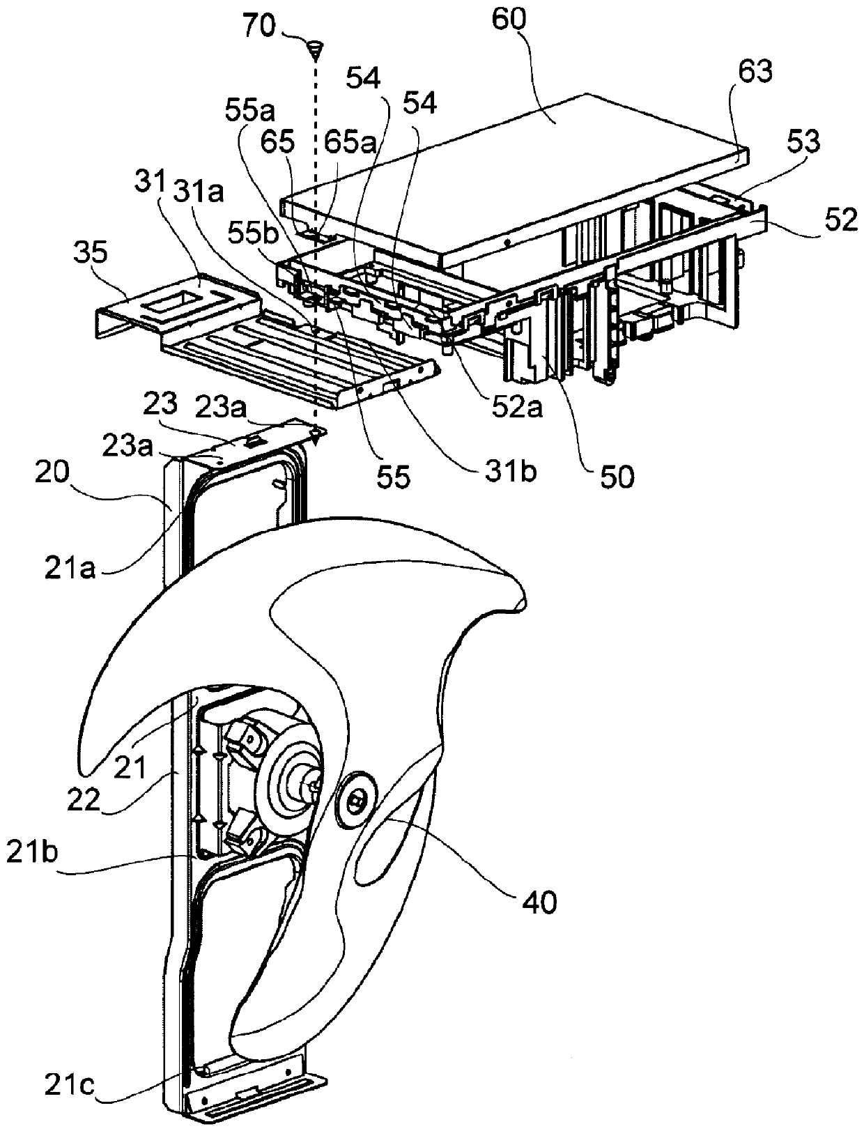
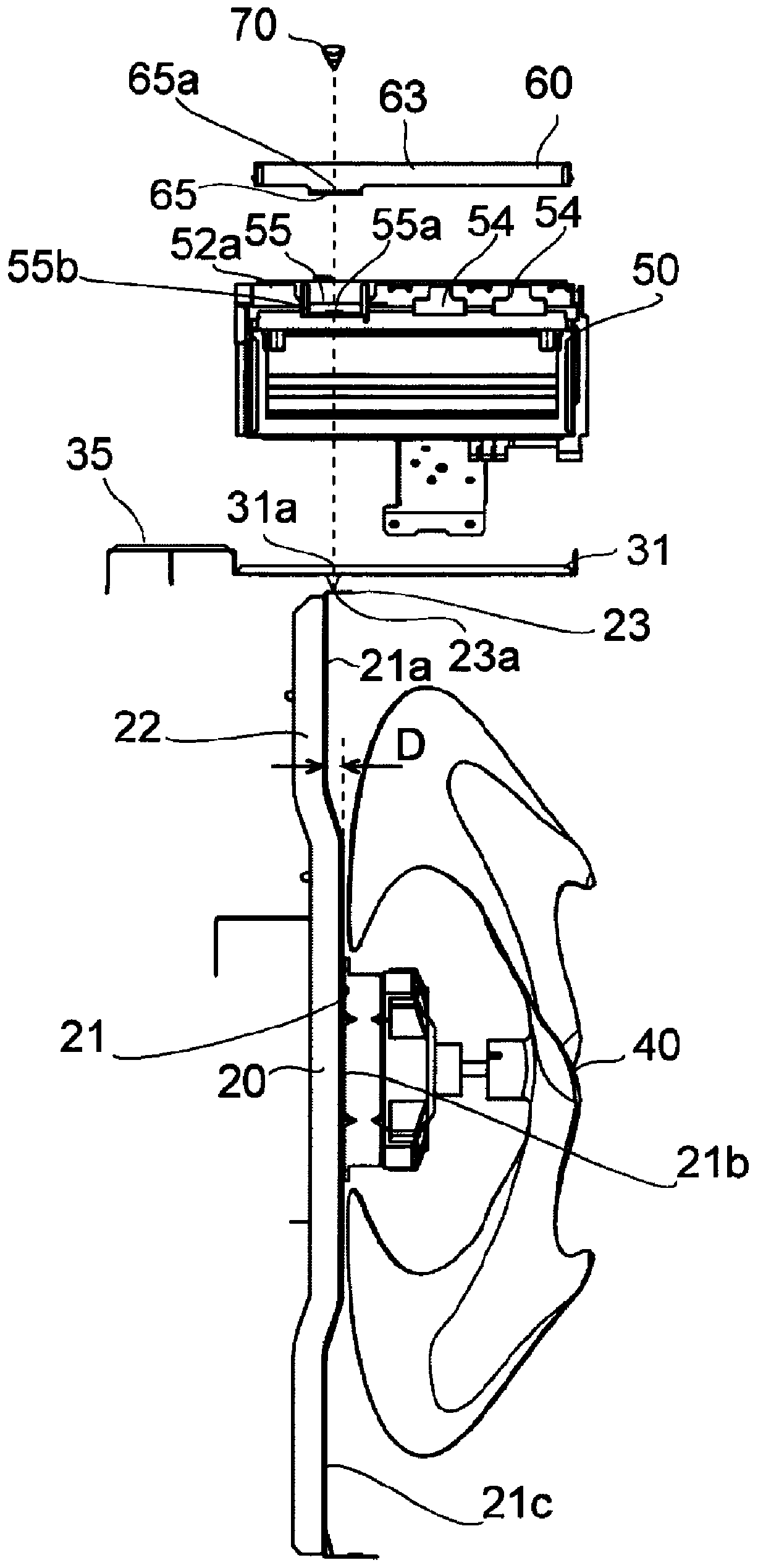
[0069] Figure 7 It is a side sectional view which shows the installation state of the electric device storage part 50 and the support plate 31 of 2nd Embodiment. In addition, the same code|symbol is attached|subjected to the same part as 1st Embodiment, and description is abbreviate|omitted. Compared with the first embodiment, the second embodiment is not provided with the locking piece 31b protruding upward from the peripheral edge on the side of the support plate 31 on the side of the electrical device receiving portion 50 (refer to Figure 6 ), and a locking hole (engaging portion) 37 is provided. The locking hole 37 is arranged at a position corresponding to the locking piece 54 , and the locking piece 54 is inserted into the locking hole 37 to be locked. Thereby, the third positioning portion for positioning the electric device housing portion 50 and the support plate 31 in the left-right direction can be easily realized.
no. 3 approach
[0071] Figure 8 It is a side cross-sectional view showing the state in which the electric device housing portion 50 and the support plate 31 are attached according to the third embodiment. In addition, the same code|symbol is attached|subjected to the same part as 1st Embodiment, and description is abbreviate|omitted. Compared with the first embodiment, in the third embodiment, one of the two locking pieces 54 arranged side by side in the front-rear direction (indicated by 54b in the figure) abuts against the peripheral edge of the support plate 31 from the side. Thereby, the third positioning portion for positioning the electric device housing portion 50 and the support plate 31 in the left-right direction can be easily realized.
[0072] This invention can be utilized for the outdoor unit of an air conditioner.
PUM
 Abstract
Description
Claims
Application Information