Supercharge Your Innovation With Domain-Expert AI Agents!

Strip steering pinch device and its follow-up structure on the entrance side of the steering roller

A technology on the turning roll and the entrance side, which is applied in the direction of metal rolling, manufacturing tools, metal processing equipment, etc., can solve the problems of increasing operating costs and maintenance costs, affecting the appearance of steel coils, and single functions, so as to save equipment installation space, Ease of production and saving of power components

Active Publication Date: 2018-07-24
WISDRI ENG & RES INC LTD
View PDF5 Cites 0 Cited by
  • Summary
  • Abstract
  • Description
  • Claims
  • Application Information

AI Technical Summary

Problems solved by technology

[0003] At present, most of the steering pinch roller devices equipped in steel mills have a single function, that is, they only have the function of steering pinch. Tail warping affects the appearance of the coil
In addition, the guide plate set on the entrance side of the steering roller is generally driven to swing by the swing drive mechanism in order to obtain a suitable swing angle of the guide plate to ensure that the advancing strip can be supported during threading and tail flicking. During normal coiling, the guide plate Does not contact the strip; the setting of the swing drive mechanism requires corresponding control elements and installation space, and increases operating and maintenance costs

Method used


Image

  • Strip steering pinch device and its follow-up structure on the entrance side of the steering roller
  • Strip steering pinch device and its follow-up structure on the entrance side of the steering roller
  • Strip steering pinch device and its follow-up structure on the entrance side of the steering roller

Examples


Embodiment Construction

[0023] The following will clearly and completely describe the technical solutions in the embodiments of the present invention with reference to the accompanying drawings in the embodiments of the present invention. Obviously, the described embodiments are only some of the embodiments of the present invention, not all of them. Based on the embodiments of the present invention, all other embodiments obtained by persons of ordinary skill in the art without making creative efforts belong to the protection scope of the present invention.

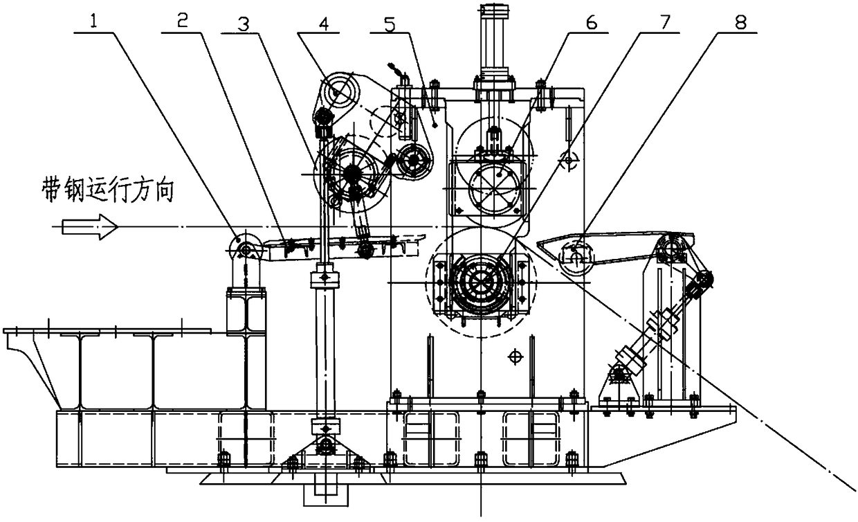
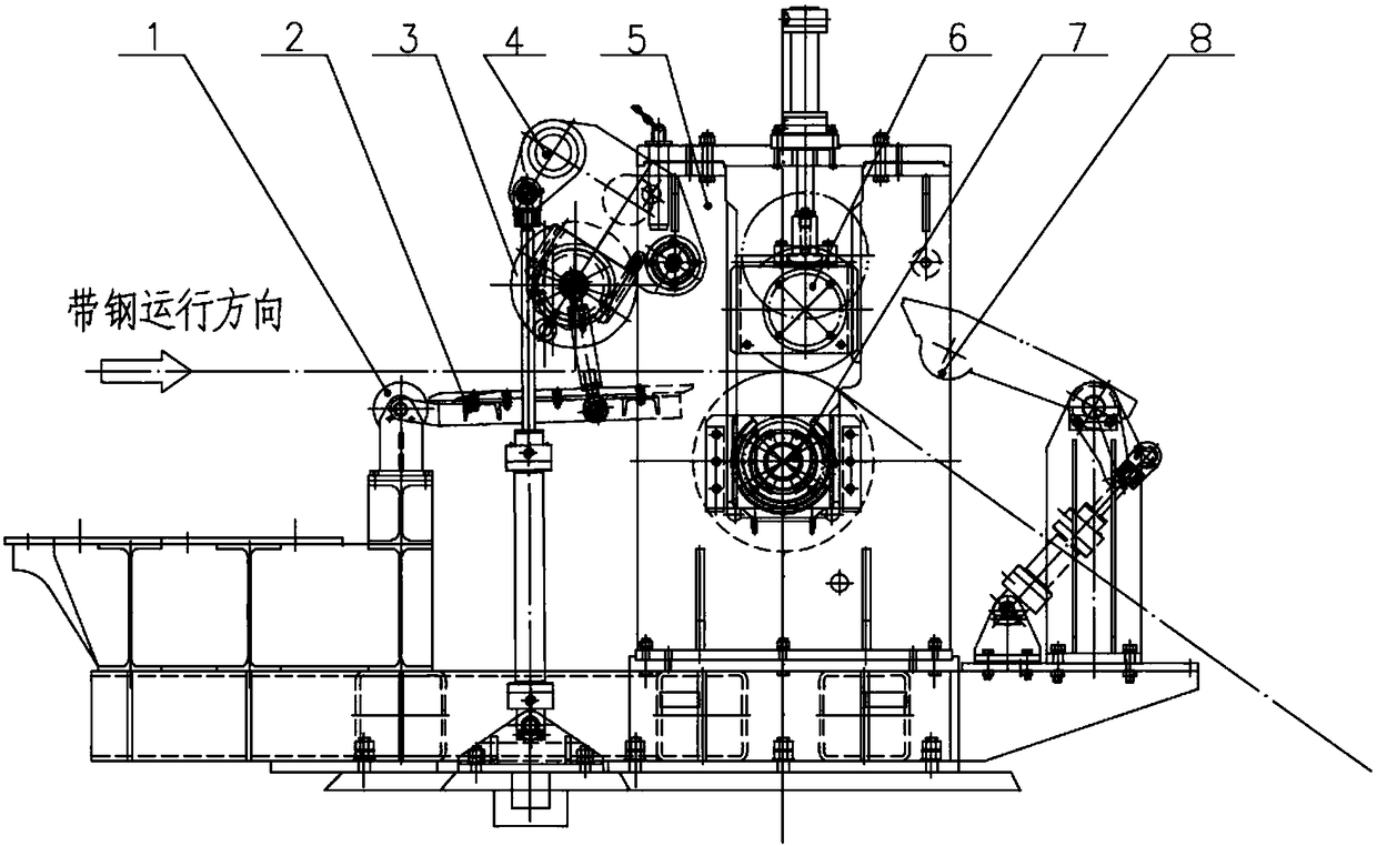
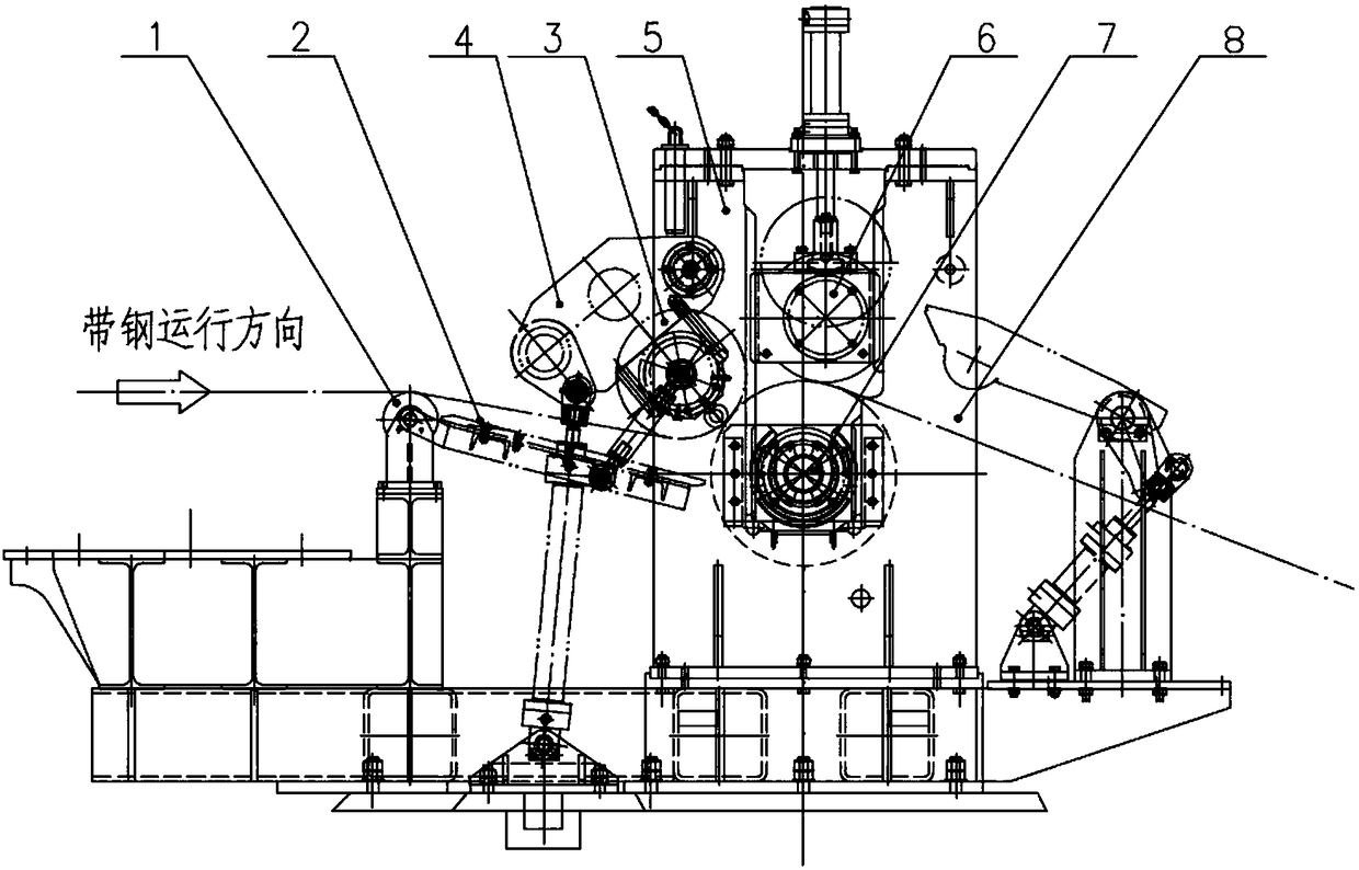
[0024] Such as Figure 1-Figure 3 , the embodiment of the present invention provides a strip turning and pinching device, including a turning roller 7 and a pinch roller unit, the turning roller 7 is installed on a frame 5, and also includes a side pressure roller 3 and a first drive mechanism ( shown in the figure, not labeled), the side pressure roller 3 is arranged on the incoming material side of the steering roller 7, and the first driving m...


PUM


Abstract

The invention relates to a strip steel steering, clamping and conveying device and a follow-up structure at the inlet side of a steering roller thereof. The follow-up structure comprises a side pressing roller and a follow-up guide plate which are arranged at the inlet side of the steering roller, and the side pressing roller is driven by a driving mechanism to move between a standby position and a pressing position; when being on the pressing position, the side pressing roller presses strip steel on the roller surface at the material incoming side of the steering roller; when being on the standby position, the side pressing roller lifts to the upside of a strip steel operation channel; and the follow-up guide plate is located below the strip steel operation channel, is rotatably connected with the side pressing roller and vertically swings along with the motion of the side pressing roller between the standby position and the pressing position. Due to the arrangement of the side pressing roller, the tail of the strip steel can be enwound and corrected in a way that the side pressing roller and the steering roller are matched to press the tail of the strip steel when the winding is about to end, so that the outer ring of a molded roll is not warped. The follow-up guide plate follows up the side pressing roller, but no independent swing driving part is needed, so that corresponding power parts and control elements can be saved, and the equipment investment as well as the operation and maintenance costs can be reduced.

Description

technical field [0001] The invention belongs to the technical field of metallurgical equipment, in particular to the technical field of steel rolling machinery, and in particular to a strip steel steering pinch device and a follower structure on the inlet side of the steering roller. Background technique [0002] At the exit section of the cold rolling continuous processing production line, before the strip enters the coiler, it must pass through a set of turning pinch rollers, and the strip head can be sent into the coiler along the specified track for edge-aligned coiling. Whether the strip steel can reach the coiler smoothly is the prerequisite for coiling. Whether the connection between each equipment is smooth is an important factor for whether the strip steel can reach the coiler smoothly; whether the strip steel can enter the coiler tongs along the designated track The mouth or coiling aid is the premise to achieve edge-aligned coiling. After the coiling is completed,...

Claims


Application Information

Patent Timeline
Patent Type & Authority Patents(China)
IPC IPC(8): B21C47/26B21C47/34B21B15/00
CPCB21B15/00B21B2015/0057B21C47/26B21C47/3433B21C47/3441
Inventor 裴艳兰张璟杨长国杨帆
Owner WISDRI ENG & RES INC LTD
Features
  • R&D
  • Intellectual Property
  • Life Sciences
  • Materials
  • Tech Scout
  • Unparalleled Data Quality
  • Higher Quality Content
  • 60% Fewer Hallucinations
Learn More