Welding device

A welding device and electric welding torch technology, applied in welding accessories, electrode support devices, characteristics of welding rods, etc., can solve the problems of potential safety hazards, simple fixing methods, low stability, etc., and achieve improved insertion stability, convenient operation, simple structure

Active Publication Date: 2017-06-20
扬州苏迈克汽车系统有限公司
View PDF3 Cites 0 Cited by
  • Summary
  • Abstract
  • Description
  • Claims
  • Application Information

AI Technical Summary

Problems solved by technology

[0002] When welding large workpieces, the welding equipment is generally fixed, and the pipe fittings are fixed on the frame and the frame moves randomly. The existing fixed welding equipment has a simple fixing method and low stability. Hidden danger

Method used


Image

  • Welding device
  • Welding device
  • Welding device

Examples


Embodiment Construction

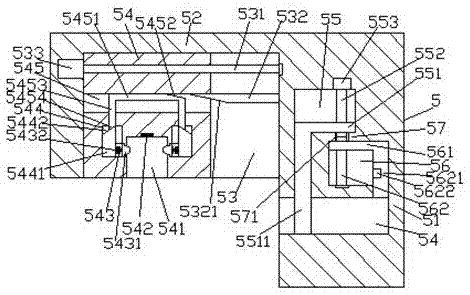
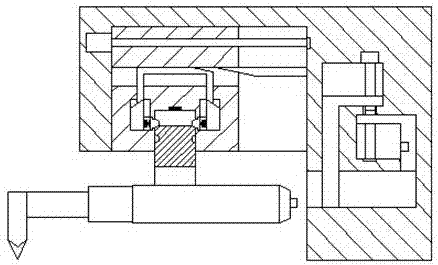
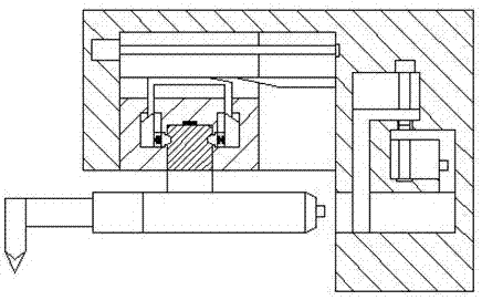
[0025] Such as Figure 1-Figure 8 As shown, a welding device of the present invention includes a fixed base 5 and an electric welding torch 6. The fixed base 5 includes a power feeding base 51 and an operation part 52 fixedly arranged on the upper left side of the power feeding base 51. An insertion groove 54 is provided in the end surface of the lower left side of the power supply seat 51, and a first sliding cavity 56 is provided in the power supply seat 51 above the right side of the insertion groove 54, and the first sliding cavity 56 is left. A second sliding chamber 55 is provided in the power supply seat 51 on the upper side, and a baffle 57 is provided between the inner top surface on the left side of the first sliding chamber 56 and the inner bottom surface on the right side of the second sliding chamber 55. The first sliding cavity 56 is provided with a first screw rod 562 extending upward, and the second sliding cavity 55 is provided with a second screw rod 552 exte...


PUM


Abstract

The invention discloses a welding device. The welding device comprises a fixed seat and an electric welding gun; the fixed seat comprises an electrifying seat and an operation part fixedly arranged above the left side of the electrifying seat; an inserting groove is formed in the end surface below the left side of the electrifying seat; a first sliding cavity is formed in the electrifying seat above the right side of the inserting groove; a second sliding cavity is formed in the electrifying seat above the left side of the first sliding cavity; a baffle is arranged between the inner top surface of the left side of the first sliding cavity and the inner bottom surface of the right side of the second sliding cavity; a first screw rod extending upwards is arranged in the first sliding cavity; a second screw rod extending downwards is arranged in the second sliding cavity; a first sliding block is connected onto the first screw rod in a thread-fit manner; a second sliding block is connected onto the second screw rod in a thread-fit manner; a first sliding groove is formed in the operation part; and a conduction screw rod extending leftwards and rightwards is arranged in the first sliding groove. The welding device is simple in structure and convenient to operate, the inserting work can be completed automatically, the efficiency, opening of a first baffle and extending of a round electrifying hole can be improved, and the safety can be improved.

Description

technical field [0001] The invention relates to the technical field of welding, in particular to a welding device. Background technique [0002] When welding large workpieces, the welding equipment is generally fixed, and the pipe fittings are fixed on the frame for welding. Hidden danger. Contents of the invention [0003] The technical problem to be solved by the present invention is to provide a welding device, which can solve the above-mentioned problems in the prior art. [0004] The present invention is achieved through the following technical solutions: a welding device of the present invention includes a fixing base and an electric welding torch, the fixing base includes a power feeding base and an operation part fixedly arranged above the left side of the power feeding base, An insertion slot is provided in the end face of the lower left side of the power feeding seat, a first sliding cavity is provided in the power feeding seat above the right side of the inser...

Claims


Application Information

Patent Timeline
Patent Type & Authority Applications(China)
IPC IPC(8): B23K9/28B23K9/32
CPCB23K9/28B23K9/32
Inventor 刘建华
Owner 扬州苏迈克汽车系统有限公司
Why Eureka
Try Eureka