
Trial Frame

一种试镜架、镜片的技术,应用在眼镜/防护镜、眼镜/护目镜、测试眼睛的设备等方向,能够解决耗时等问题

Inactive Publication Date: 2017-06-20
OCULUS OPTIKGERATE GMBH
View PDF11 Cites 3 Cited by
  • Summary
  • Abstract
  • Description
  • Claims
  • Application Information

AI Technical Summary

Problems solved by technology

These necessary manufacturing steps are also relatively time-consuming

Method used


Image

  • Trial Frame
  • Trial Frame
  • Trial Frame

Examples


Embodiment Construction

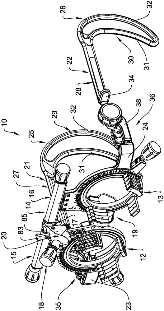
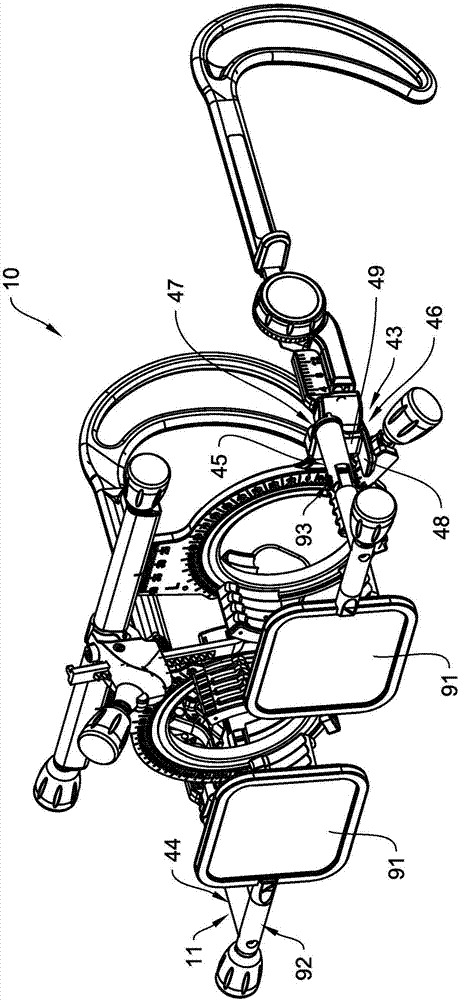
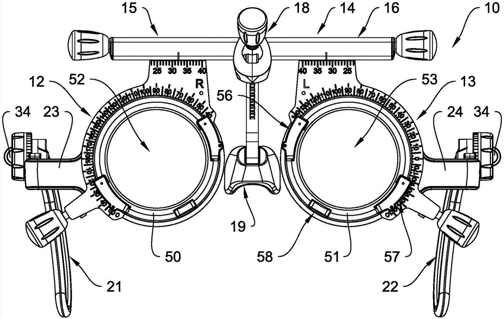
[0056] Figure 1 to Figure 7 The combined view of shows the trial frame 10 in different views. exist figure 2 In the illustration of FIG. 6 , the polarizing filter device 11 of the trial frame 10 is attached to the trial frame. The trial frame 10 is used to measure the subject's or patient's subjective refraction (not shown in the figure). Accordingly, the orientation and position terms below are always relative to the body plane of the subject wearing the adjusted trial frame 10 . The trial frame 10 comprises two lens holder devices 12 and 13 and a nose piece 14 for receiving an inserted lens (not shown in the figure) and a nose piece 14 which makes the lens holder devices 12 and 13 face each other in a lateral direction connected at a distance from each other in an individually adjustable manner. The nosepiece 14 is formed by two nosepiece parts 15 and 16 which are firmly connected to each other by a pivot axis 17 . Thus, the lens holder device 12 is adjustably attache...


PUM


Abstract

The invention relates to a trial frame for determining the subjective refraction of a subject, comprising two lens holder devices for receiving insert lenses, a bridge, which connects the lens holder devices in such a manner that their distance relative to each other is adjustable, a nose rest device having a pivotable and height-adjustable nose rest and two temples, which are adjustable in length and height, the nose rest device having an adjustment gear for adjusting the height of the nose rest, the adjustment gear having a toothed rack and a bevel worm wheel, which are engaged with each other.

Description

technical field [0001] The invention relates to a trial frame for determining subjective refraction of a subject comprising two lens holder devices for receiving an inserted lens in such a manner that their distance relative to each other is adjustable Connected nose bridge, nose pad device with pivotable and height-adjustable nose pads, and two temples adjustable in length and height, nose pad device with an adjustment gear mechanism for adjusting the height of the nose pads . Background technique [0002] Such trial frames are typically used for testing ophthalmic lenses. To do this, the trial frame is adapted to the subject, ie the person, and an easily replaceable insert lens or trial lens is inserted into the trial frame. The insert lenses are arranged in a rotatable manner so as to be able to correct astigmatic defects along their axial position. The lateral and height defects corrected by the prism must also be adjustable, which is why the trial frame must be preci...

Claims


Application Information

Patent Timeline
Patent Type & Authority Applications(China)
IPC IPC(8): G02C13/00A61B3/11
CPCA61B3/111G02C13/003A61B3/04A61B3/0075G02B5/30
Inventor 卡斯滕·费尔塔格
Owner OCULUS OPTIKGERATE GMBH
Learn More