
Wireless communication apparatus and transmission control method

a communication apparatus and transmission control technology, applied in the field of wireless communication apparatus, can solve the problems of error generally occurring in the second half portion of the aggregated frame, and no study has been made on a technique for selecting both transmission rates

Active Publication Date: 2010-03-02
KK TOSHIBA
View PDF9 Cites 0 Cited by
  • Summary
  • Abstract
  • Description
  • Claims
  • Application Information

AI Technical Summary

Benefits of technology

The present invention provides a wireless communication apparatus that can select the best transmission rate and frame length for transmitting an aggregated frame based on the throughput obtained with each trial transmission rate and reference frame length. The apparatus can also determine whether communication is possible or not based on the response received and set the initial / maximum values of the transmission rate and frame length for transmitting the aggregated frame accordingly. This improves the efficiency of wireless communication.

Problems solved by technology

On the other hand, as the frame length increases excessively, the wireless channel state estimated at the head of a frame differs from the state at the rear half portion of the frame, resulting in an error.
For this reason, a channel state corresponding to frames of the second half portion of the aggregated frame differs from the channel state at the time of estimation from the preamble, and hence errors generally tend to occur in the frames of the second half portion of the aggregated frame.
However, no studies have been made on a technique for selecting both a transmission rate and the number of frames in an aggregated frame from the viewpoint of throughput.

Method used


Image

  • Wireless communication apparatus and transmission control method
  • Wireless communication apparatus and transmission control method
  • Wireless communication apparatus and transmission control method

Examples


first embodiment

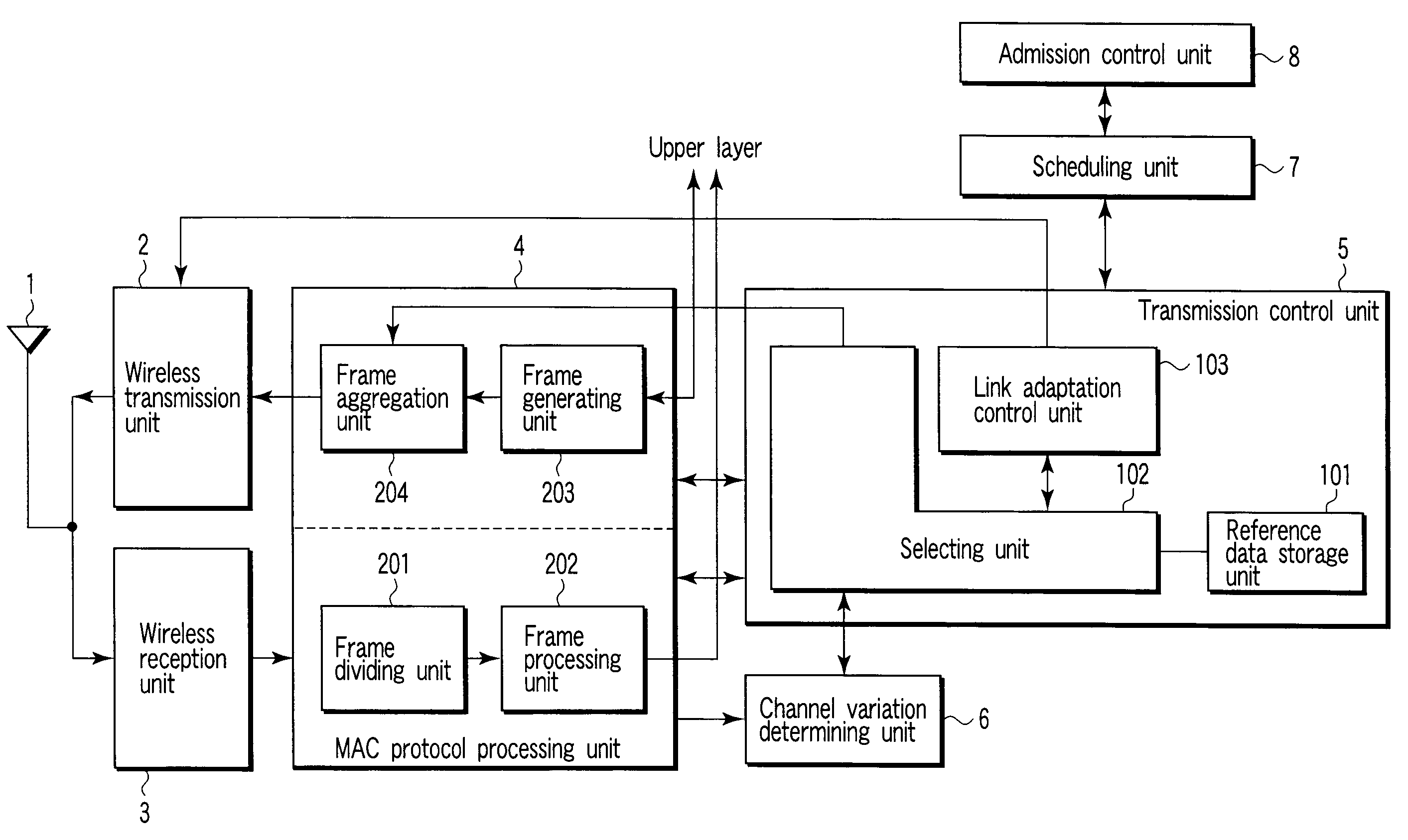
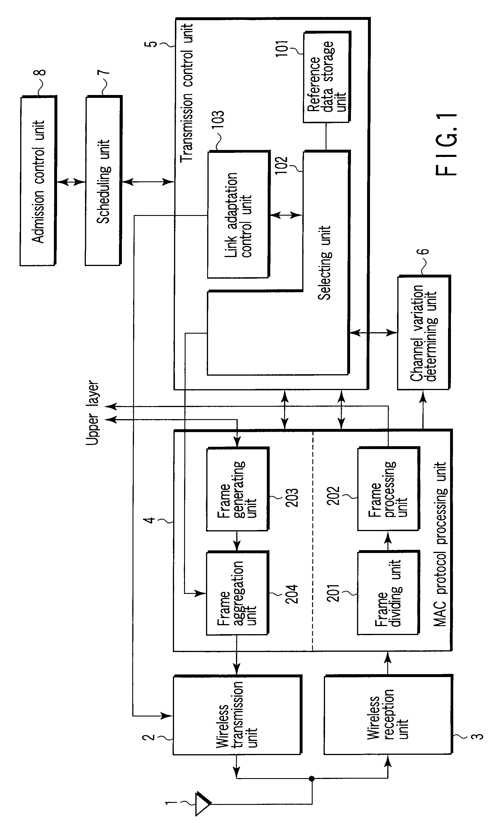
[0029]A wireless communication apparatus in FIG. 1 includes at least an antenna 1, wireless transmission unit 2, wireless reception unit 3, MAC protocol processing unit 4, transmission control unit 5, channel variation determining unit 6, scheduling unit 7, and admission control unit 8.

[0030]The MAC protocol processing unit 4 includes a frame dividing unit 201, frame processing unit 202, frame generating unit 203, and frame aggregation unit 204. The transmission control unit 5 includes a reference data storage unit 101, selecting unit 102, and link adaptation control unit 103.

[0031]An outline of the operation of the wireless communication apparatus in FIG. 1 at the time of signal transmission will be described first.

[0032]The admission control unit 8 performs a series of procedures for inquiring whether it is possible to communicate with a desired communication apparatus such as an access point (AP), e.g., notifying the communication apparatus of a usable transmission rate. If there...

second embodiment

[0084]Another processing operation for selecting a frame length and a transmission rate will be described next with reference to the flowchart shown in FIG. 6. Note that the same reference numerals as in FIG. 5 denote the same parts in FIG. 6, and different portions will be described below. That is, step S12′ in FIG. 6 replaces step S12 in FIG. 5, and steps S26 to S28 in FIG. 6 replace step S16 in FIG. 5.

[0085]In step S12 in FIG. 5, the selecting unit 102 selects the highest transmission rate among a plurality of transmission rate candidates. In contrast, in step S12′ in FIG. 6, a selecting unit 102 selects a transmission rate at which communication can be actually performed from a plurality of transmission rate candidates.

[0086]If, for example, the maximum transmission rate among a plurality of transmission rate candidates is 104 MB / s, the selecting unit 102 selects a transmission rate of 52 Mb / s in step S12′. If the apparatus performs trial communication by using a transmission ra...

third embodiment

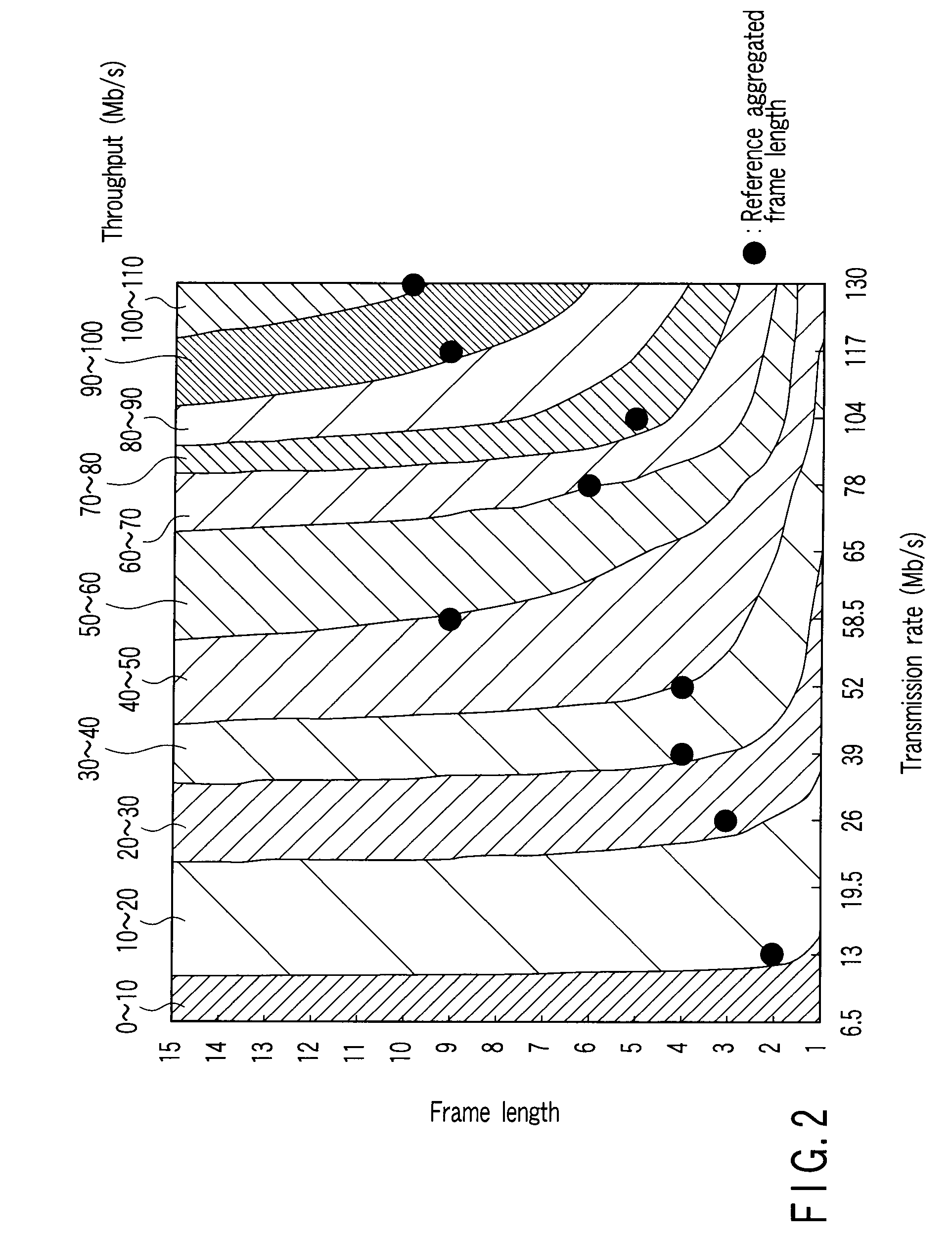
[0094]In the first and second embodiments, the reference data stored in the reference data storage unit 101 may include frame lengths other than reference aggregated frame lengths and information indicating the corresponding throughputs, together with the reference aggregated frame lengths, with respect to the respective transmission rates, as shown in, for example, FIG. 7.

[0095]Referring to FIG. 7, each column corresponds to a transmission rate (Mb / s), and each row represents a corresponding throughput (Mb / s). The numerical value in each cell represents the number of frames in an aggregated frame. In the columns corresponding to the respective transmission rates, some cells having encircled numerical values. These encircled numerical values represent reference aggregated frame lengths at the respective transmission rates.

[0096]Obviously from FIG. 7, if the number of frames at a transmission rate of 52 Mb / s is “4”, the obtained throughput is 40 to 50 Mb / s.

[0097]In this manner, it su...


PUM


Abstract

A wireless communication apparatus includes a memory to store reference data including transmission rates usable for transmission of an aggregated frame including frames and reference frame lengths of the aggregated frame corresponding to the transmission rates, respectively, a throughput obtained with one of the transmission rates and a reference frame length of the reference frame lengths which corresponds to the one of the transmission rates is higher than any throughputs obtained with any frame length at another transmission rate lower than the one of the transmission rates, selects a trial transmission rate and corresponding reference frame length as a trial frame length, sets the trial transmission rate and the trial frame length, with which communication is determined to be possible by transmitting a trial aggregated frame, to initial / maximum values of a transmission rate for transmitting the aggregated frame and a frame length of the aggregated frame, respectively.

Description

CROSS-REFERENCE TO RELATED APPLICATIONS[0001]This application is based upon and claims the benefit of priority from prior Japanese Patent Application No. 2006-150540, filed May 30, 2006, the entire contents of which are incorporated herein by reference.BACKGROUND OF THE INVENTION[0002]1. Field of the Invention[0003]The present invention relates to a wireless communication apparatus.[0004]2. Description of the Related Art[0005]A wireless system uses a technique of transmitting a plurality of frames upon aggregating them to improve communication efficiency. For example, Task Group n (TGn), whose standardization has been under way via IEEE801.11, has proposed an aggregation technique of aggregating and transmitting a plurality of frames. This technique of aggregating and transmitting a plurality of frames can reduce overheads such as physical (PHY) and MAC layer headers accompanying each frame, which are required at the time of transmission and reception of frames, and the interval bet...

Claims


Application Information

Patent Timeline
Patent Type & Authority Patents(United States)
IPC IPC(8): H04W4/00H04L47/36H04L47/43H04W24/06H04W28/06H04W72/04H04W84/12
CPCH04W28/22
Inventor MATSUO, RYOKO
Owner KK TOSHIBA
Learn More