A power system of an internal combustion engine with a pendulum block and an inner cavity cam rotor

A technology of internal combustion engine and cam rotor, applied in the direction of internal combustion piston engine, combustion engine, machine/engine, etc., can solve the problems of limited scalability of triangular rotor internal combustion engine structure, difficult to improve rotor shaft torque, and difficult to improve combustion utilization rate. , to achieve the effect of short motion transmission link, simple structure and low manufacturing cost

Active Publication Date: 2019-06-25
DALIAN UNIV OF TECH
View PDF6 Cites 0 Cited by
  • Summary
  • Abstract
  • Description
  • Claims
  • Application Information

AI Technical Summary

Problems solved by technology

However, there are still key problems such as high processing requirements for core parts, too sensitive to wear, difficult adjustment of compression ratio, low thermal efficiency, etc., and it is still difficult to improve the combustion utilization rate
At the same time, similar to the piston internal combustion engine, the scalability of the triangular rotor internal combustion engine structure is also limited
In addition, when the expansion force generated by the fuel is converted into the power of the output shaft, there are natural defects in the transmission of force
Although the expansion force can push the rotor to rotate, it is difficult to increase the torque of the resultant force on the rotor shaft, and the proportion of internal friction is also too high

Method used


Image

  • A power system of an internal combustion engine with a pendulum block and an inner cavity cam rotor
  • A power system of an internal combustion engine with a pendulum block and an inner cavity cam rotor
  • A power system of an internal combustion engine with a pendulum block and an inner cavity cam rotor

Examples


Embodiment 1

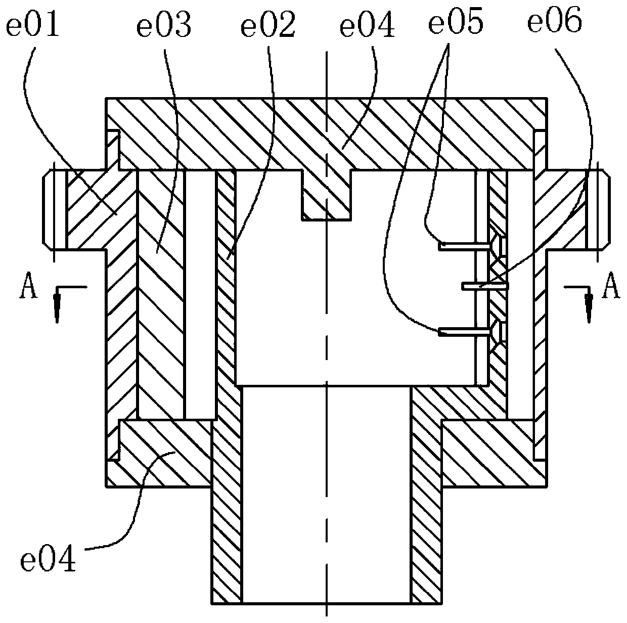
[0045] See attached image 3 , assuming that the central member is a fixed cylinder, the cam member in the inner cavity is a rotor, and there is a disc cam cavity with a near rest area and a far rest area, and both the near and far angles of repose are slightly less than 180°. The quantity of pendulum block is 2, symmetrically arranged. The overall sealing relationship of the assembly is as before, and will not be repeated. There is a small cylindrical surface in the center of the pendulum block, and a part of the concentric sealing cylindrical surface is also provided at the free end. There are two air inlets and two air outlets, which are located inside the central component and are separated between the two pendulum blocks. They are all represented by switches, and the one with a small circle on the handle is the air inlet valve. A pair of intake and exhaust ports are one group, and along the direction of rotation of the inner chamber cam indicated by the hollow arrow, the...

Embodiment 2

[0057] and then pass Figure 4 and 5 Demonstrate a slightly more complex situation.

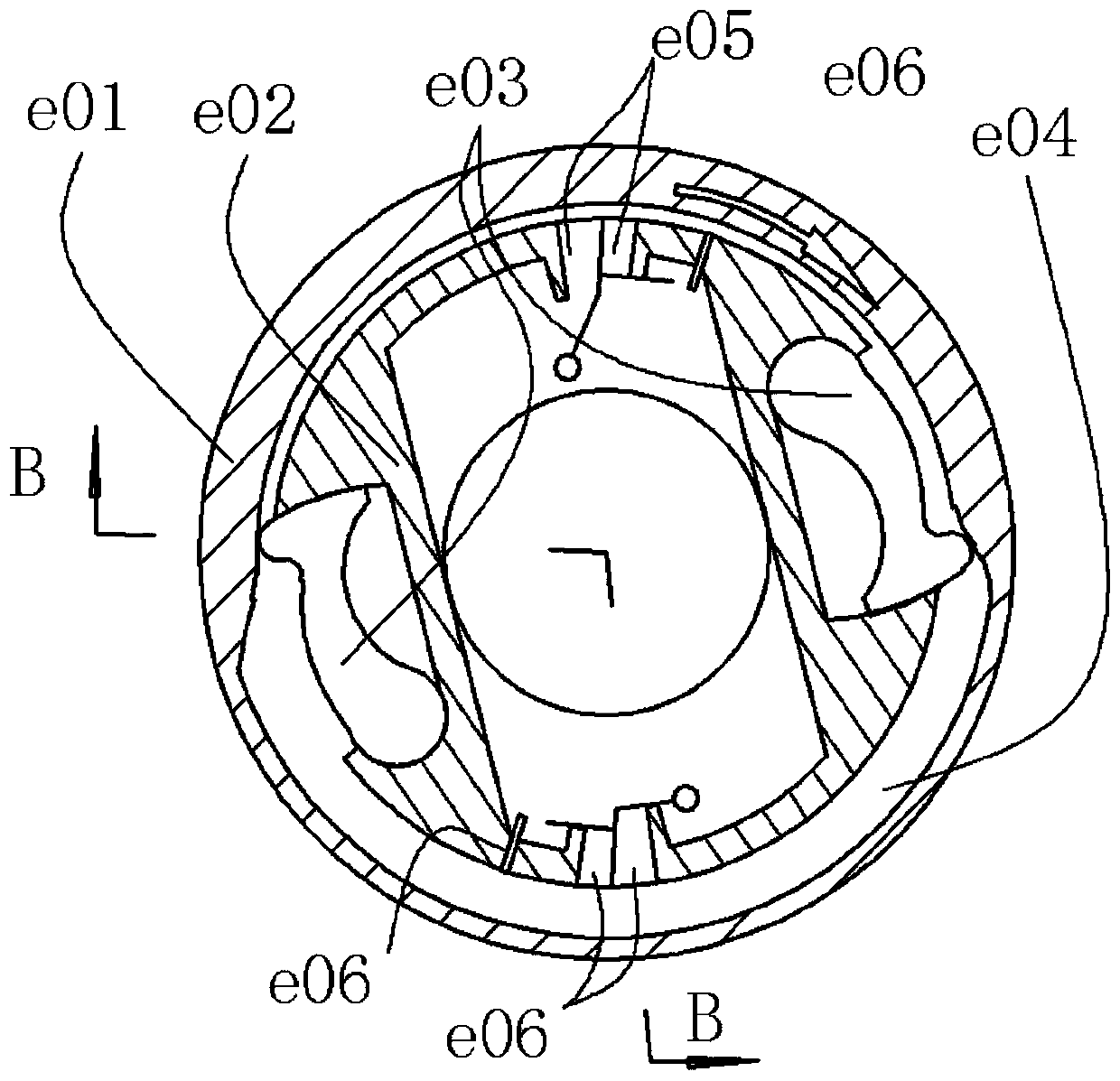
[0058] The center member is fixed, and the inner chamber cam member having the inner chamber cam profile is used as the rotor. There are three pendulum blocks on the central member, and its outer surface is evenly divided into three sections. The pendulum block adopts the equivalent arc groove pendulum block form. The cam profile of the inner cavity has a near rest area and a far rest area. The angle of repose Generally as shown in the figure, that is, the near rest area of ​​the inner cavity cam contour is similar to the corresponding central angle between the two pendulum blocks, and the space between the two pendulum blocks is the working chamber or combustion chamber. Figure 4 and 5 The corresponding valve state and the working process in the chamber are shown in different positions of the inner chamber cam member rotor. Same as the previous example, there are three working chambers,...

Embodiment 3

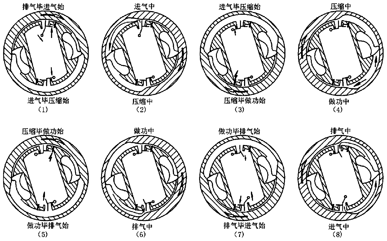
[0069] Figure 6 Show variability further.

[0070] As long as the circumferential space is large enough, the number of pendulum blocks and the number of inner cam protrusions (such as the near-rest area) can be increased arbitrarily. With the addition of the pendulum escapement, the size of the working space for completing each working cycle can also be changed.

[0071] The parameter relationships selected below are only for the convenience and clarity of description, and are not limiting. In the figure, it is assumed that there are two near-rest sections of the inner cavity cam rotor evenly distributed, and the arc length of the near-rest section is slightly larger than the corresponding arc length of the two adjacent pendulum blocks, so that the two pendulum blocks can be in the retracted state at the same time. The number of pendulum blocks is taken as 6 and evenly distributed, indicated by numbers. Each pendulum is controlled by the pendulum escapement, where "out of ...


PUM


Abstract

The invention discloses an internal combustion engine power system for matching a swing block with an inner cavity cam rotor, belongs to the field of internal combustion engines, and relates to the internal combustion engine power system for matching the swing block with the inner cavity cam rotor. In the power system, the inner cavity cam rotor is used for forming a cam mechanism with multiple swing driven pieces mounted on a center component in a cavity, and is used for forming multiple peripherally distributed sealed working cavities with end components; the sealed working cavities are changeable in volumes along with relative rotation of the inner cavity cam rotor and the center component; valves are arranged in a cooperation mode to finish four processes of intake, compression, acting and exhaust of the Otto cycle therein; and chemical energy generated by gas combustion is directly converted to mechanical energy in a relative fixed shaft rotating mode of the inner cavity cam rotor and the center component. High-pressure gas directly pushes a rotor fixed shaft to rotate and to output power; and the system is simple in structure and wide in parameter adjusting range. Under longitudinal capturing control of additional swing block, the system is liable to realize flexible control; and compared with a triangular rotor internal combustion engine power system, the system has more prominent advantages.

Description

technical field [0001] The invention belongs to the field of internal combustion engines, and relates to a power system of an internal combustion engine with a pendulum block and an inner cavity cam rotor. Background technique [0002] The piston internal combustion engine is the earliest internal combustion engine that came out. Its characteristic is that the piston makes a reciprocating linear motion in the cylinder, and the output of the crankshaft rotary motion is realized through the crank slider mechanism. Within two weeks of crankshaft rotation, the cylinder completes a complete intake, compression, work, and exhaust four working processes, that is, the Otto cycle. It is generally believed that the piston internal combustion engine has the advantages of high thermal efficiency, compact structure, strong maneuverability, and easy operation and maintenance. It is even believed that the power device of the piston internal combustion engine, especially the mechanical str...

Claims


Application Information

Patent Timeline
Patent Type & Authority Patents(China)
IPC IPC(8): F02B53/00F02B55/02F02B55/08F02B53/06F02B53/02
CPCF02B53/00F02B53/02F02B53/06F02B55/02F02B55/08Y02T10/12
Inventor 孙守林卞永宁洪鹏飞杨扬王琳张光临
Owner DALIAN UNIV OF TECH
Why Eureka
Try Eureka