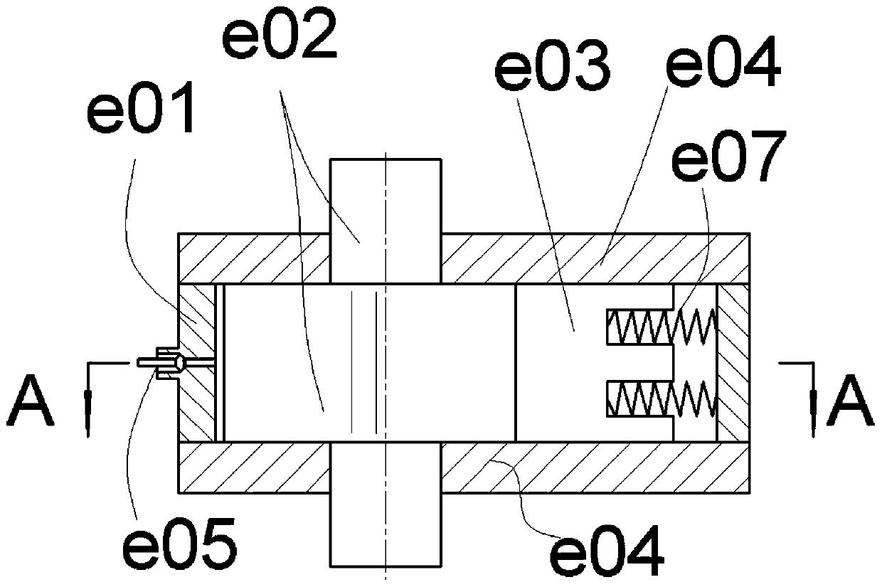
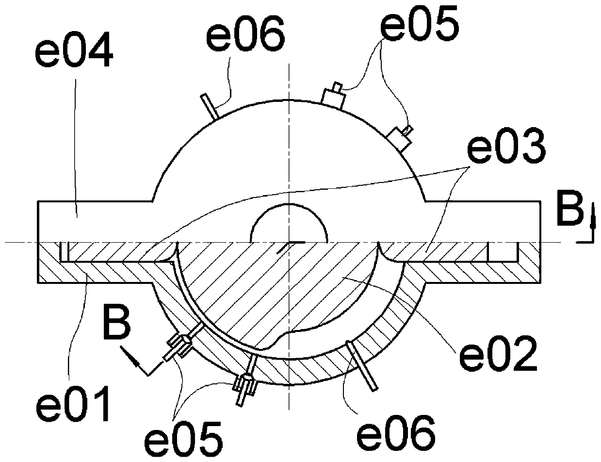
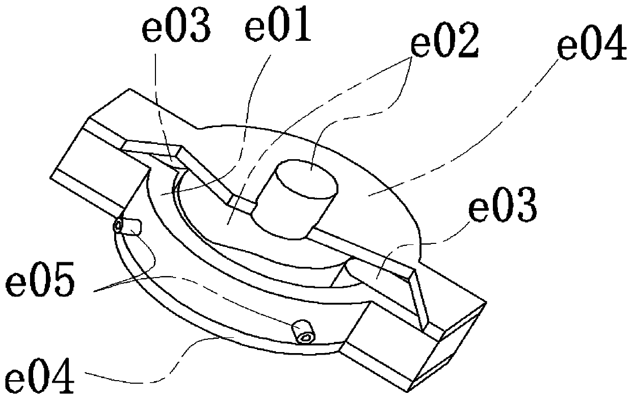
A sliding block combined with a cam rotor internal combustion engine power system
A technology for internal combustion engines and cam rotors, applied to internal combustion piston engines, combustion engines, machines/engines, etc., can solve the problems of limited scalability of triangular rotor internal combustion engines, difficulty in improving rotor shaft torque, and high processing requirements for core parts. To achieve the effect of short motion transmission link, simple structure and large parameter range
- Summary
- Abstract
- Description
- Claims
- Application Information
AI Technical Summary
Problems solved by technology
Method used
Image
Examples
Embodiment 1
[0047] See attached Figure 4 , assuming that the rotor housing is fixed, the cam rotor is a disc cam with a far rest zone and a near rest zone, and the far and near rest angles are slightly less than 180°. The number of sliders is 2, arranged symmetrically. After assembly, the sealing relationship is the same as before and will not be repeated. There are two air inlets and two air outlets respectively, which are located on the rotor chamber and are located on both sides of the slider. They are all indicated by switch symbols, and the ones with small circles are air inlets. A pair of intake and exhaust ports is one group, along the cam rotation direction indicated by the arrow, the air intake port is in front of the same group, and the exhaust port is not limited. There are two ignition devices.
[0048] The two sliders divide the rotor and the rotor chamber into two left and right working chambers. Since the volumes of the two chambers change simultaneously when the rotor ...
Embodiment 2
[0057] and then pass Figure 5 with 6 Demonstrate a slightly more complex situation.
[0058] The rotor housing is fixed, and the cam rotor with cam profile is used as the output member. There are three sliders on the rotor housing to divide the rotor housing evenly into three sections. The cam rotor has a far rest area and a near rest area respectively. The corresponding central angles are similar, and the space between the two sliders is the working chamber or combustion chamber. Figure 5 with 6 It shows the corresponding valve state and working process in the chamber at different positions of the rotor. Same as the previous example, there are three working chambers, each chamber has two possible working processes at the beginning, so there are 8 different combined working modes. Only two are shown here, and the rest will not be discussed one by one.
[0059] First mode:
[0060] Figure 5 It starts from the combination state of the three processes of starting air i...
Embodiment 3
[0069] Figure 7 Show variability further. As long as the circumferential space is large enough, the number of sliders and the number of cam protrusions (such as the far rest area) can be increased arbitrarily. With the addition of a slider escapement, the size of the working space to complete each working cycle can also be varied.
[0070] The parameter relationships selected below are only for the convenience and clarity of description, and are not limiting. In the figure, it is assumed that the far resting sections of the cam rotor are two evenly distributed, and the arc length of the resting sections is slightly larger than the corresponding arc lengths of the two adjacent sliders, so that the two sliders are retracted at the same time. The number of sliders is taken as 6 and evenly distributed, indicated by numbers. Each slider is controlled by the slider escapement, where "out of control" means that the slider has been released by the escapement, "controlled" means th...
PUM
 Abstract
Description
Claims
Application Information
 - R&D
- Intellectual Property
- Life Sciences
- Materials
- Tech Scout
- Unparalleled Data Quality
- Higher Quality Content
- 60% Fewer Hallucinations
Browse by: Latest US Patents, China's latest patents, Technical Efficacy Thesaurus, Application Domain, Technology Topic, Popular Technical Reports.
© 2025 PatSnap. All rights reserved.Legal|Privacy policy|Modern Slavery Act Transparency Statement|Sitemap|About US| Contact US: help@patsnap.com


