System and method for detecting defects on reflection surface through visual system

A visual system and reflective technology, applied in the field of visual systems for inspecting reflective surfaces

Active Publication Date: 2017-07-18
COGNEX CORP
View PDF5 Cites 22 Cited by
  • Summary
  • Abstract
  • Description
  • Claims
  • Application Information

AI Technical Summary

Problems solved by technology

However, this technique has limitations for installation and use in enviro...

Method used


Image

  • System and method for detecting defects on reflection surface through visual system
  • System and method for detecting defects on reflection surface through visual system
  • System and method for detecting defects on reflection surface through visual system

Examples


Embodiment Construction

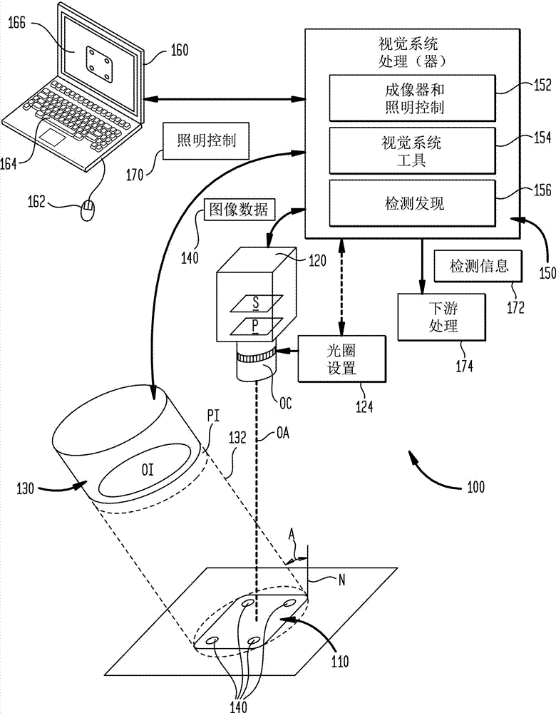
[0031] figure 1 is an illustration of an exemplary vision system arrangement 100 in which a scene includes a reflective object 110 positioned stationary relative to a stationary vision system camera 120 in accordance with an illustrative embodiment. In this embodiment, vision system camera 120 includes a two-dimensional (2D) image sensor S that includes an array of N×M pixels in, for example, a rectangular arrangement. The camera includes an optical package OC, which may include any acceptable lens assembly (eg, a lens with a C-type objective mount, F-type objective mount, or M12-type mount). In this embodiment, the lens includes a manual or automatic aperture control—for example, an iris, wherein a user or other external controller can enter an appropriate aperture setting 124 into the manual or automatic aperture control (as further described below). like that). Sensor S and optical package OC collectively define an optical axis OA, which is generally perpendicular to the ...


PUM


Abstract

The invention relates to a system and a method for detecting and imaging reflection surface defects on a reflection surface through a blade edge technology. A camera aperture or an external device is arranged to form a physical blade edge structure in an optical path. The physical blade edge structure advantageously shields reflection rays from an illuminated reflection surface which has a preset slope value, and makes rays deflecting by different slopes reach a visual system camera sensor. Most light reflected from a flat part on a surface is blocked by the blade edge. Most light reflected from a defective slope part is reflected to an entrance aperture. An illumination beam forms a certain angle relative to the optical axis of the camera, to provide an incidence angle which is proper for an examined surface. The surface can be static or move relative to the camera.

Description

[0001] Cross references to related patent applications [0002] This application claims the rights and interests of the following application documents: the title of "System and Method for DETECTING DEFECTS ON ASPECULAR SURFACE WITH A VISION SYSTEM)" submitted on November 13, 2015, Pending U.S. Provisional Application Serial No. 62 / 255,360; filed December 31, 2015, titled SYSTEMAND METHOD FOR DETECTING DEFECTS ON A SPECULAR SURFACE WITH A SPECULAR SURFACE WITH A VISION SYSTEM VISION SYSTEM)", U.S. provisional application serial number No. 62 / 274,094; and filed on October 5, 2016, entitled "SYSTEM AND METHOD FOR DETECTING DEFECTS ON A SPECULAR SURFACE WITH A VISION SYSTEM), U.S. Provisional Application Serial No. 62 / 404,431, the teachings of which are expressly incorporated herein by reference. technical field [0003] The present invention relates to machine vision systems for inspecting surfaces of objects, and more particularly, to vision systems for inspecting reflective s...

Claims


Application Information

Patent Timeline
IPC IPC(8): G01N21/88G01N21/89G01N21/892G01N21/01
CPCG01N21/01G01N21/8806G01N21/8851G01N21/8901G01N21/8903G01N21/8914G01N21/892G01N2021/0112G01N2021/8829G01N2021/8841G01N2021/8848G01N2021/8887G01N2021/8908G01N2021/8924G01N21/21G02B27/149
Inventor F·罗斯塔米J·F·菲尔哈伯F·钱
Owner COGNEX CORP
Why Eureka
Try Eureka