A mechanical arm tooling mechanism for nut assembly in a narrow space
A narrow space, inner nut technology, used in metal processing, manufacturing tools, metal processing equipment, etc., can solve the problems of difficult to guarantee assembly quality, low work efficiency, limited space, etc., to ensure accuracy, continuity, and maintenance. Input and output effects
- Summary
- Abstract
- Description
- Claims
- Application Information
AI Technical Summary
Problems solved by technology
Method used
Image
Examples
specific Embodiment approach 1
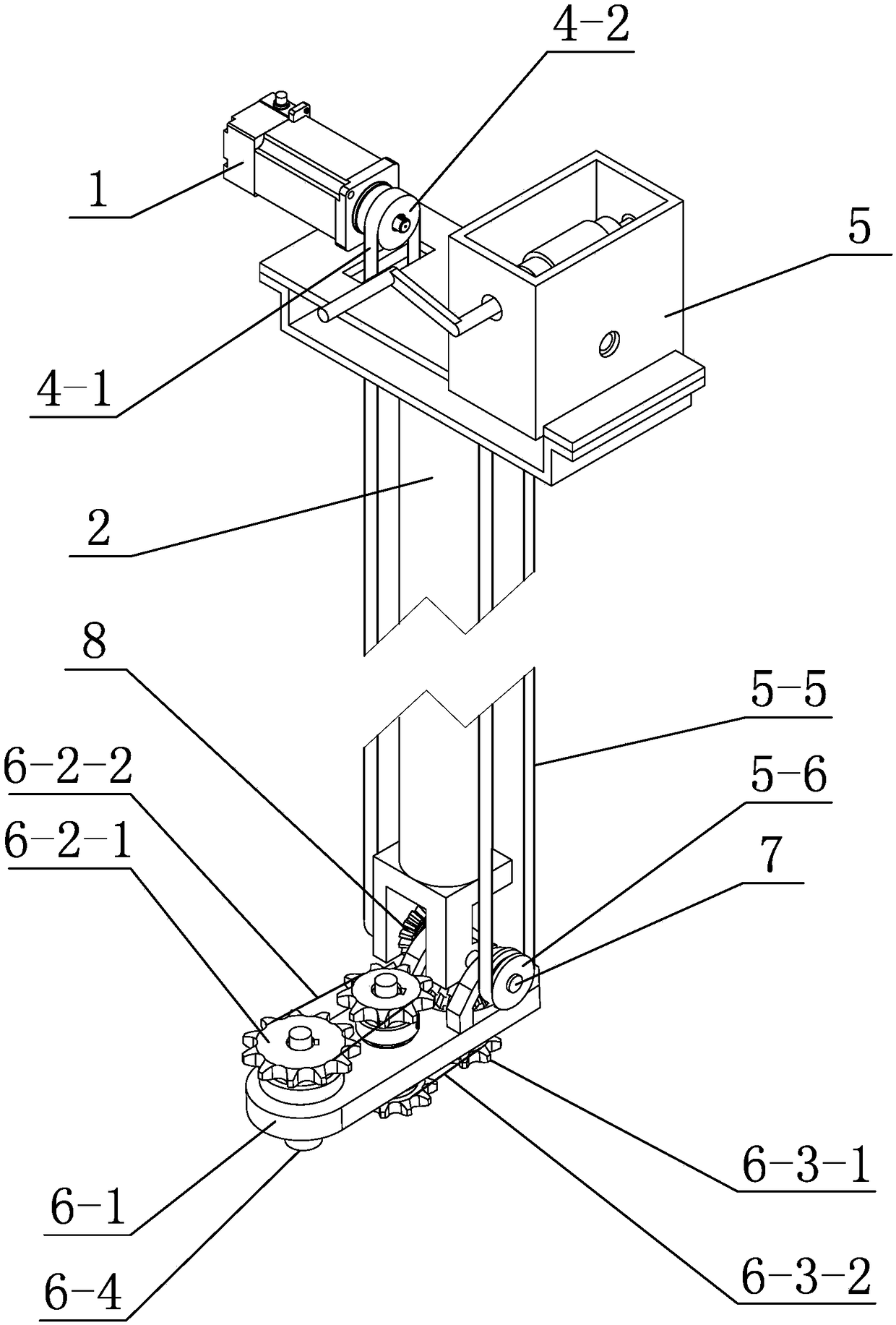
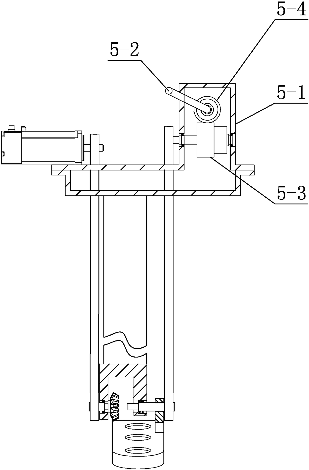
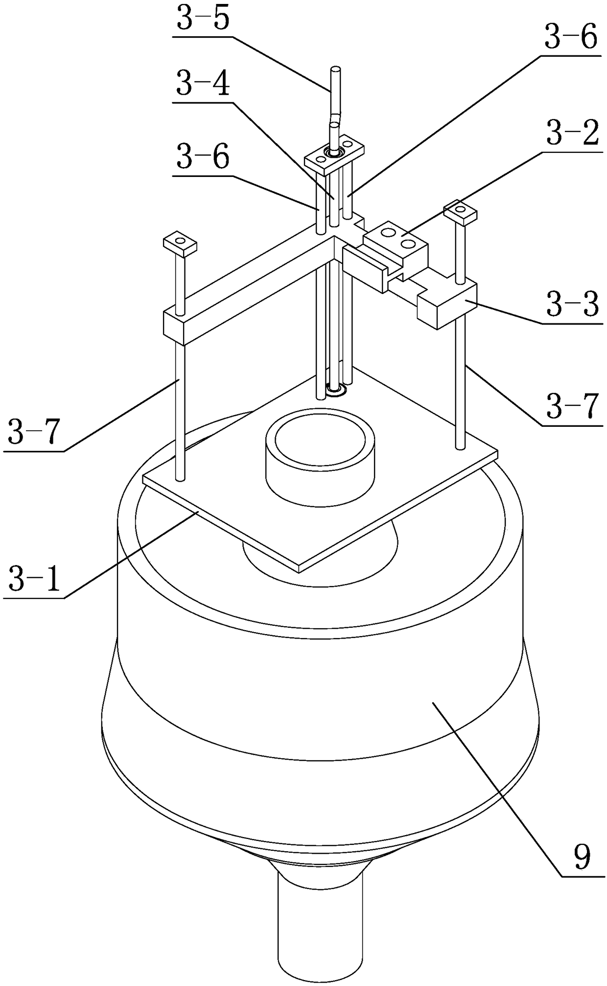
[0039] Specific implementation mode one: combine figure 1 , figure 2 , image 3 , Figure 4 , Figure 5 , Figure 6 , Figure 7 , Figure 8 , Figure 9 , Figure 10 , Figure 11 , Figure 12 and Figure 13 Describe this embodiment, this embodiment includes motor 1, support assembly 2, lifting mechanism 3, transmission mechanism 4, attitude control mechanism 5 and actuator 6, described lifting mechanism 3 is arranged at the entrance of narrow space, and support assembly 2 is arranged On the lifting mechanism 3, the support assembly 2 reciprocates up and down along the height direction of the lifting mechanism 3 under the control of the lifting mechanism 3, the actuator 6 is hinged at the bottom of the support assembly, the motor 1 is arranged on the support assembly 2, and the motor 1 passes The transmission mechanism 4 is connected with the actuator 6 , the actuator 6 is driven by the attitude control mechanism 5 to make a rotation action, and the actuator 6 is dri...
specific Embodiment approach 2
[0041] Specific implementation mode two: combination image 3 , Figure 4 , Figure 5 , Figure 6 , Figure 8 and Figure 10 Describe this embodiment. In this embodiment, the lifting mechanism 3 includes a base plate 3-1, a calibration seat 3-2, a moving table 3-3, a screw 3-4, a first rocking handle 3-5, and two intermediate polished rods 3-2. 6 and two end polished rods 3-7, the bottom plate 3-1 is horizontally arranged, and an assembly port is processed on the bottom plate 3-1, and the bottom plate 3-1 is arranged at the entrance of the narrow space through the assembly port, and the two middle The polished rods 3-6 and the two end polished rods 3-7 are vertically arranged side by side on the base plate 3-1, the mobile platform 3-3 is arranged horizontally, and the mobile platform 3-3 passes through the two intermediate polished rods 3-6 and the two One end polished rod 3-7, the mobile platform 3-3 is slidingly matched with two middle polished rods 3-6 and two end poli...
specific Embodiment approach 3
[0045] Specific implementation mode three: combination figure 1 , figure 2 , Figure 5 , Figure 7 , Figure 9 , Figure 11 and Figure 12 Describe this embodiment, in this embodiment, the actuator 6 includes a main board 6-1, an upper sprocket assembly 6-2, a lower sprocket assembly 6-3 and a nut sleeve 6-4, and one end of the main board 6-1 is connected to end, the other end of the main board 6-1 is a movable end, the connecting end of the main board 6-1 is hinged on the bottom of the support assembly 2 through the connecting column 7, and the upper sprocket assembly 6-2 is arranged on the upper surface of the main board 6-1 , the lower sprocket assembly 6-3 is arranged on the lower end surface of the main board 6-1, one upper transmission wheel 6-2-1 in the upper sprocket assembly 6-2 and one lower transmission wheel in the lower sprocket assembly 6-3 6-3-1 is coaxially connected, the nut sleeve 6-4 is located at the lower end surface of the main board 6-1 and is arr...
PUM
 Abstract
Description
Claims
Application Information
 - R&D
- Intellectual Property
- Life Sciences
- Materials
- Tech Scout
- Unparalleled Data Quality
- Higher Quality Content
- 60% Fewer Hallucinations
Browse by: Latest US Patents, China's latest patents, Technical Efficacy Thesaurus, Application Domain, Technology Topic, Popular Technical Reports.
© 2025 PatSnap. All rights reserved.Legal|Privacy policy|Modern Slavery Act Transparency Statement|Sitemap|About US| Contact US: help@patsnap.com


