A drawer type power switch cabinet device

A power switch and drawer-type technology, applied in the field of power equipment, can solve problems such as hidden safety hazards, forward tilt of the cabinet, loss of the cabinet, etc., and achieve the effects of high safety, avoiding the risk of rollover and simple structure

Active Publication Date: 2018-12-14
山东永锦电气股份有限公司
View PDF7 Cites 0 Cited by
  • Summary
  • Abstract
  • Description
  • Claims
  • Application Information

AI Technical Summary

Problems solved by technology

At this time, because the center of gravity of the drawer moves forward, the center of gravity of the cabinet body is moved forward, so it is easy to cause the cabinet body to lean forward, and the overturning of the cabinet body will cause great losses. Therefore, there is a great potential safety hazard

Method used


Image

  • A drawer type power switch cabinet device
  • A drawer type power switch cabinet device
  • A drawer type power switch cabinet device

Examples


Embodiment Construction

[0013] Combine below Figure 1-3 The present invention will be described in detail.

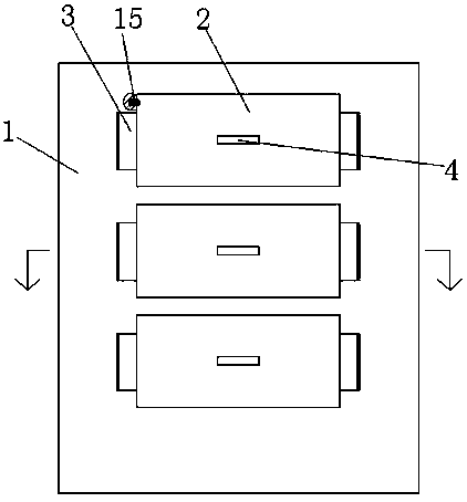
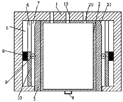
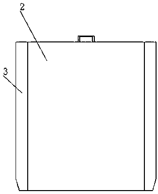
[0014] refer to Figure 1-3 According to the present invention, a drawer-type power switchgear device includes a cabinet body 1, a plurality of installation slots arranged in the cabinet body 1 and separated up and down, and installed in the installation slots and used for installing components. A plurality of drawer boxes 2, sliding grooves are symmetrically arranged on both sides of each installation groove, and sliding grooves are arranged on the outside of the sliding grooves, and the sliding grooves include a first guide groove 5 on the outside, a second guide groove 6 in the middle, and Inside the empty slot 7, a gear 9 is installed in the middle part of the empty slot 7, a counterweight 8 is slidably installed in the middle part of the first guide slot 5, and the front end of the second guide slot 6 is slidably installed There is a sliding bar 10, the inner end surface of the sliding...


PUM


Abstract

A drawer type power switch cabinet device includes a cabinet body (1), a plurality of mounting grooves arranged in the cabinet body and vertically separated from one another, and a plurality of drawer boxes (2) mounted in the mounting grooves and for mounting components. Each mounting groove is provided with sliding grooves symmetrically in both sides. Each sliding groove is provided with a gliding groove in the outer side. Each gliding groove consists of a first guide groove (5) in the outer side, a second guide groove (6) in the intermediate portion and an empty groove (7) in the inner side. A gear (9) is mounted on the intermediate portion of each empty groove. The intermediate portion of each first guide groove (5) is slidably equipped with a balancing weight (8). The front end of each second guide groove (6) is slidably equipped with a sliding bar (10). The end face on the inner side of each sliding bar is provided with a driven gear portion which is engaged with the corresponding gear. The rear end of the end face on the outer side of the each sliding bar (10) is fixedly connected with the corresponding balancing weight (8). The left and right end faces of each of the drawer boxes (2) are symmetrically provided with sliding arms matching the sliding grooves.

Description

technical field [0001] The invention relates to the field of electric equipment, in particular to a drawer-type power switch cabinet device. Background technique [0002] Power installation cabinets are common components in the field of power and electrical sensor control. The power electrical control cabinet is used to install various sensors, controllers and other components for power control. In order to facilitate maintenance and installation, the power installation cabinet usually has drawers for pushing and pulling to maintain the components inside. [0003] Many drawers often need to be installed, and when maintenance is required, one of them often needs to be pulled out. At this time, because the center of gravity of the drawer moves forward, the center of gravity of the cabinet body is moved forward, so it is easy to cause the cabinet body to lean forward, and the overturning of the cabinet body will cause great losses, so there is a great potential safety hazard....

Claims


Application Information

Patent Timeline
Patent Type & Authority Patents(China)
IPC IPC(8): H02B11/173
CPCH02B11/173
Inventor 钟潘霄
Owner 山东永锦电气股份有限公司
Why Eureka
Try Eureka