Pick-up camera

A camera lens and lens technology, applied in the field of camera lens, can solve the problems of f-θ distortion correction, affecting spatial positioning accuracy, negative distortion, etc., and achieve the effect of correcting f-θ distortion

Active Publication Date: 2017-08-08
ZHEJIANG SUNNY OPTICAL CO LTD
View PDF9 Cites 9 Cited by
  • Summary
  • Abstract
  • Description
  • Claims
  • Application Information

AI Technical Summary

Problems solved by technology

However, under a large field of view, negative distortion will occur, which directly affects the accuracy of spatial positioning.
However, conventi

Method used


Image

  • Pick-up camera
  • Pick-up camera
  • Pick-up camera

Examples


Embodiment 1

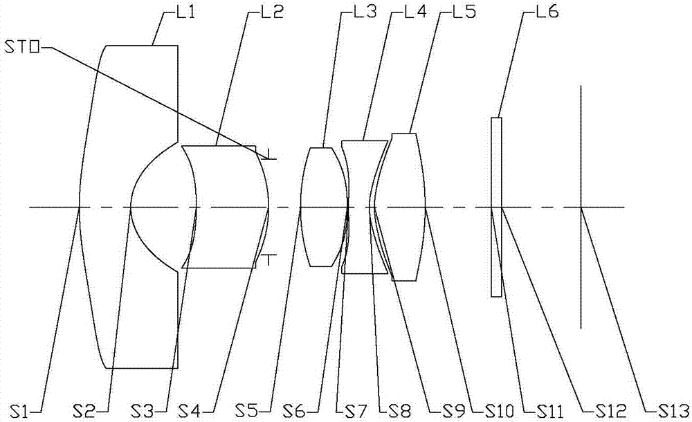
[0067] Refer to the following Figure 1 to Figure 2D The imaging lens according to Embodiment 1 of the present application is described. figure 1 A schematic structural diagram of the imaging lens according to Embodiment 1 of the present application is shown.

[0068] like figure 1 As shown, the imaging lens includes a first lens L1 , a second lens L2 , a third lens L3 , a fourth lens L4 , a fifth lens L5 and an imaging surface S13 in sequence from the object side to the imaging side along the optical axis.

[0069] The first lens L1 has negative refractive power, the object side S1 is convex, the image side S2 is concave, and both the object side S1 and the image side S2 of the first lens L1 are aspherical; the second lens L2 has positive refractive power, The object side S3 is concave, the image side S4 is convex, and the object side S3 and the image side S4 of the second lens L2 are both aspherical; the third lens L3 has positive refractive power, the object side S5 is co...

Embodiment 2

[0088] Refer to the following Figures 3 to 4D The imaging lens according to Embodiment 2 of the present application is described. In this embodiment and the following embodiments, descriptions similar to those in Embodiment 1 will be omitted for the sake of brevity. image 3 A schematic structural diagram of the imaging lens according to Embodiment 2 of the present application is shown.

[0089] like image 3 As shown, the imaging lens includes a first lens L1 , a second lens L2 , a third lens L3 , a fourth lens L4 , a fifth lens L5 and an imaging surface S13 in sequence from the object side to the imaging side along the optical axis.

[0090] The first lens L1 has negative refractive power, the object side S1 is concave, the image side S2 is concave, and the object side S1 and the image side S2 of the first lens L1 are both aspherical; the second lens L2 has positive refractive power, The object side S3 is convex, the image side S4 is convex, and the object side S3 and th...

Embodiment 3

[0103] Refer to the following Figures 5 to 6D The imaging lens according to Embodiment 3 of the present application is described. Figure 5 A schematic structural diagram of the imaging lens according to Embodiment 3 of the present application is shown.

[0104] like Figure 5 As shown, the imaging lens includes a first lens L1 , a second lens L2 , a third lens L3 , a fourth lens L4 , a fifth lens L5 and an imaging surface S13 in sequence from the object side to the imaging side along the optical axis.

[0105] The first lens L1 has negative refractive power, the object side S1 is concave, the image side S2 is concave, and the object side S1 and the image side S2 of the first lens L1 are both aspherical; the second lens L2 has positive refractive power, The object side S3 is concave, the image side S4 is convex, and the object side S3 and the image side S4 of the second lens L2 are both aspherical; the third lens L3 has positive refractive power, the object side S5 is conve...


PUM


Abstract

The application discloses a pick-up camera which has a total effective focal length and includes from an object side to an image side along an optical axis: a first lens, a second lens, a third lens, a fourth lens and a fifth lens. The first lens has a negative power and a concave image side surface. The second lens has a positive power or a negative power and has a convex image side surface. The third lens has a positive power or a negative power, and has a convex image side surface. The fourth lens has a negative power and has a convex image side surface. The fifth lens has a positive power or a negative power. The third power has an effective focal length f3 which has a relationship with the effective focal length f5 of the fifth lens: 1<f3/f5<1.9. The radius of curvature R6 of the third lens and the total effective focal length f of the pick-up camera meet the following relationship: -2.5<R6/f<-1.6.

Description

technical field [0001] The present application relates to a photographic lens, and more particularly, the present application relates to a photographic lens including five lenses. Background technique [0002] Along with the development of science and technology, portable electronic product rises gradually, especially the portable electronic product with camera function gets people's more favor. In recent years, camera lenses using CCD or CMOS as photosensitive elements have been widely used in various fields, not only for obtaining images, but also for spatial positioning. In space positioning applications, it is generally desired that the lens has a larger field of view to capture a larger range of image information, so that a wider space can be positioned. This requires that the camera lens for spatial positioning needs to have a large field of view. However, under a large field of view, negative distortion will occur, which directly affects the accuracy of spatial posi...

Claims


Application Information

Patent Timeline
IPC IPC(8): G02B13/00G02B13/06G02B13/18
CPCG02B13/0045G02B13/06G02B13/18
Inventor 黄林王新权
Owner ZHEJIANG SUNNY OPTICAL CO LTD
Why Eureka
Try Eureka