Projection lens and projection system

A technology of projection lens and projection beam, which is applied in the field of optical projection, can solve the problems of unfavorable lens miniaturization and increase of total optical length, and achieve the effect of reducing total optical length and satisfying large viewing angle

Pending Publication Date: 2019-01-29
IVIEW DISPLAY SHENZHEN CO LTD
View PDF0 Cites 9 Cited by
  • Summary
  • Abstract
  • Description
  • Claims
  • Application Information

AI Technical Summary

Problems solved by technology

[0004] The inventors of the present invention found in the process of implementing the embodiments of the present invention that the current waveguide projection lens or other near-eye display device applications need to meet the imaging requirements of a l

Method used


Image

  • Projection lens and projection system
  • Projection lens and projection system
  • Projection lens and projection system

Examples


Example Embodiment

[0029] Example one

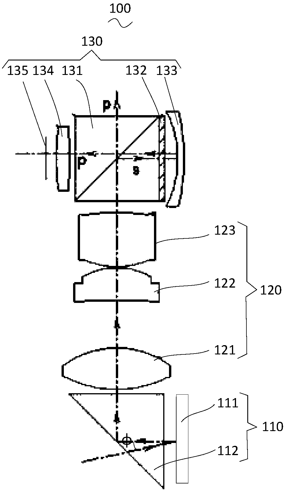
[0030] See figure 1 , Is a schematic structural diagram of a projection lens provided by one of the embodiments of the present invention. Such as figure 1 As shown, the projection lens 100 includes a guiding display element group 110, a lens element group 120, and a reflective optical element group 130.

[0031] Wherein, the lens element group 120 is provided between the guide display element group 110 and the reflective optical element group 130, and the guide display element group 110 is used to convert an illumination beam incident from a first direction into a projection beam, and to make the projection beam move toward the second direction. The lens element group 120 is used to receive and guide the projection light beam output by the display element group 110, and the reflective optical element group 130 is used to make the projection light beam emerge from a third direction. Through the above method, the direction of the light beam is changed, thereby ...

Example Embodiment

[0058] Example two

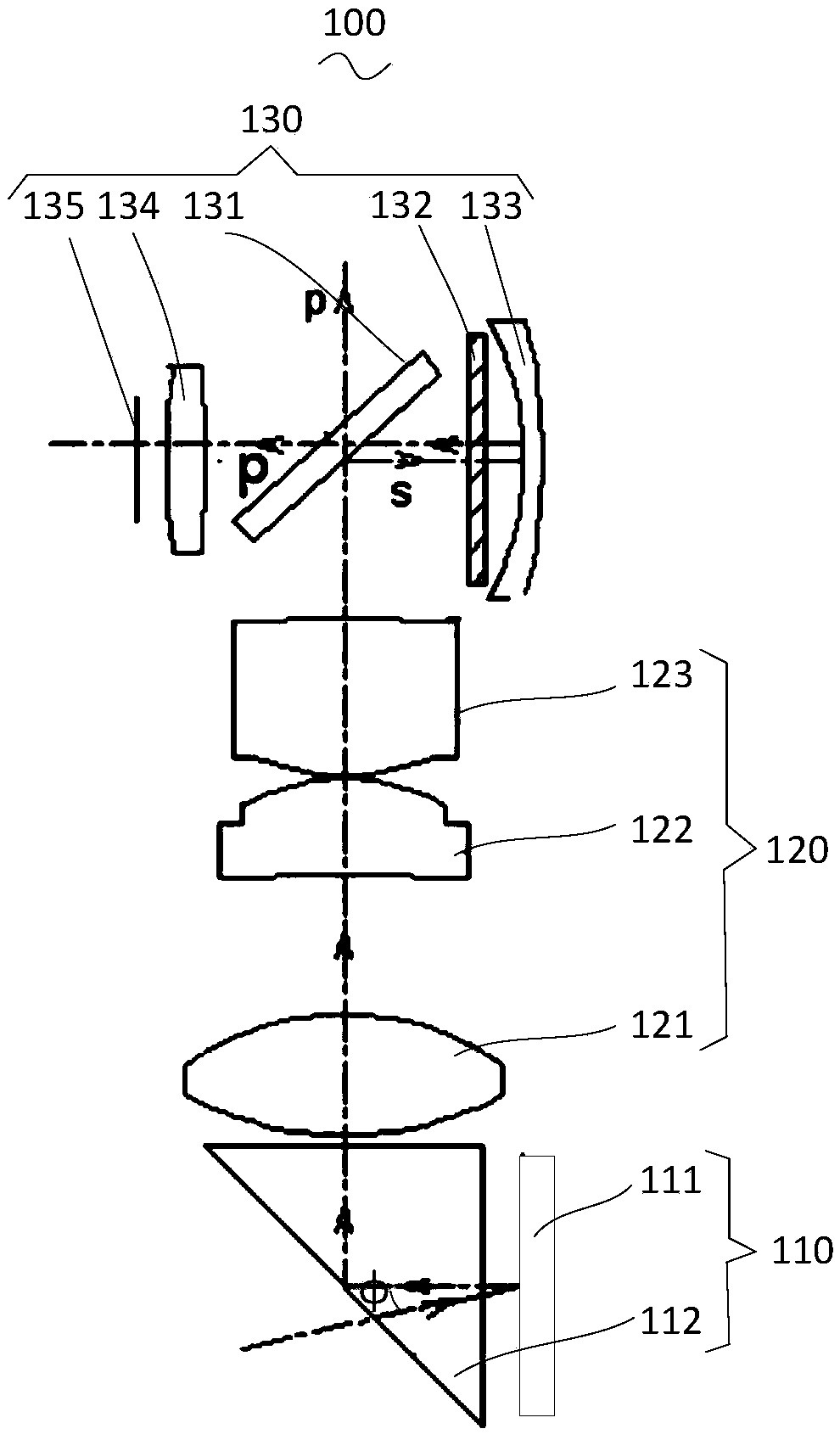
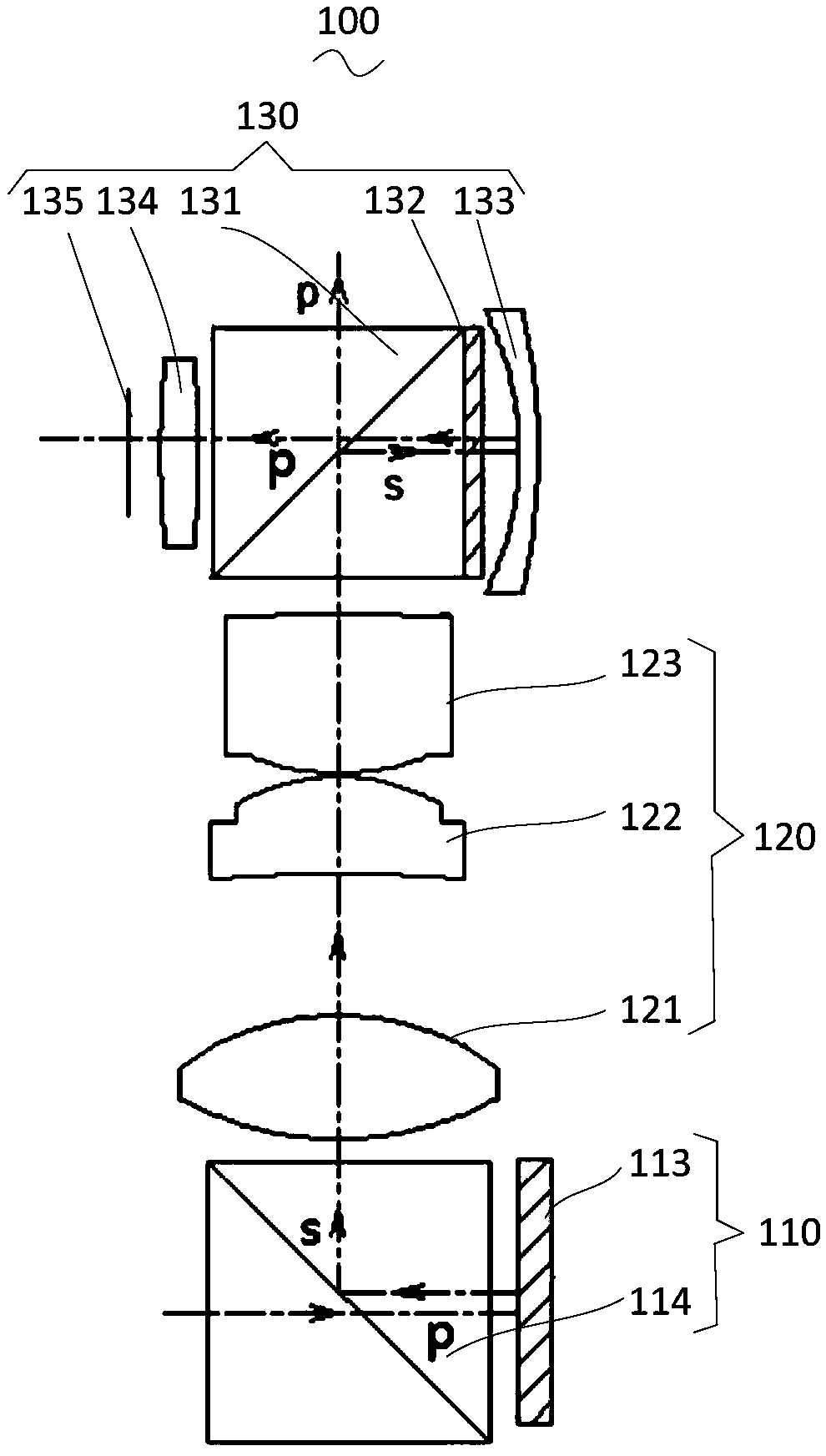
[0059] See Figure 3a , Is a schematic structural diagram of a projection lens provided by another embodiment of the present invention. Such as Figure 3a As shown, the difference from the first embodiment is that the guiding display element group 110 includes: a second display chip 113 and a second polarization splitting element 114.

[0060] Among them, the second display chip 113 is an LCOS display chip, and the second display chip 113 is used to convert part of the illumination beam output by the second polarization beam splitting element 114 into the first polarized light of the projection beam and output it to the second polarization beam splitter Component 114.

[0061] Wherein, the second polarization beam splitting element 114 is a polarization beam splitting prism, the polarization beam splitting prism is cemented by a pair of high-precision right-angle prisms, one of the prisms is coated with a polarization beam splitting film on the inclined surface...

Example Embodiment

[0066] Example three

[0067] See Figure 4 , Is a schematic structural diagram of a projection system provided by an embodiment of the present invention. Such as Figure 4 As shown, the projection system 200 includes an illuminating device 210 and the projection lens 100 in the first embodiment or the second embodiment described above. The illuminating device 210 is used to provide an illuminating light beam for the projection lens 100.

[0068] Among them, in this embodiment, implementation 1 is taken as an example for illustration.

[0069] Wherein, the illuminating device 210 may be a laser light source, such as a fiber coupled laser light source, a diode laser light source, or a solid laser light source. The illuminating device 210 may include a red laser light source, a green laser light source, and a blue laser light source. By using three primary color lasers, the illuminating device 210 can make the projection lens 100 most realistically reproduce the rich and gorgeous c...


PUM


Abstract

The embodiment of the invention relates to the technical field of optical projection, and discloses a projection lens and a projection system. The projection lens comprises a guiding display componentgroup, a lens component group and a reflection optical component group, wherein the guiding display component group is used for converting an illumination light beam incident from a first direction into a projection light beam and enabling the projection light beam to emit in a second direction; the lens component group is used for receiving and transmitting the projection light beam output by the guiding display component group; and the reflection optical component group includes a first polarization beam splitting component, a quarter-wave plate and a curved surface reflector, the first polarization beam splitting component is arranged at the light emitting side of the lens component group, the quarter-wave plate and the curved surface reflector are arranged at one side of the first polarization beam splitting component, and the quarter-wave plate is arranged between the first polarization beam splitting component and the curved surface reflector. According to the above mode, the embodiment of the invention can reduce the total optical length of the device and guarantee the satisfaction of imaging quality such as a large view angle.

Description

Technical field [0001] The embodiments of the present invention relate to the field of optical projection technology, and in particular to a projection lens and a projection system. Background technique [0002] In recent years, near-eye display technologies such as augmented reality technology have been rapidly developed, for example, Microsoft's HoloLens (a holographic computer device that is not limited by cables), Sony's holographic see-through technology glasses, and so on. Augmented reality near-eye display technology is a technology that images a light field in a real space, which can realize the interaction between the virtual world and the real world. [0003] At present, the solution of realizing augmented reality technology through optical waveguides is widely used. This solution can reduce the volume and quality of the device and realize the directional transmission of light. [0004] In the process of implementing the embodiments of the present invention, the inventor o...

Claims


Application Information

Patent Timeline
IPC IPC(8): G03B21/14G03B21/20
CPCG03B21/142G03B21/206G03B21/2066G03B21/2073
Inventor 高志强杨伟樑赵远林清云蒲小凤
Owner IVIEW DISPLAY SHENZHEN CO LTD
Why Eureka
Try Eureka