

Shooting optical system
A photographic optical system and image-side technology, applied in the field of photographic optical systems, can solve problems such as difficult chromatic aberration correction and affecting imaging quality, and achieve the effects of reducing system sensitivity, good imaging quality, and shortening the total length of the lens
- Summary
- Abstract
- Description
- Claims
- Application Information
AI Technical Summary
Problems solved by technology
Method used
Image

Examples
no. 1 example 》
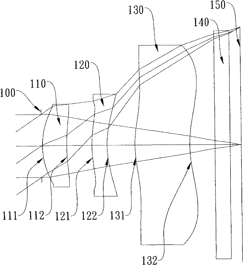
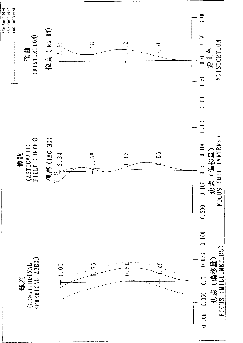
[0095] Please refer to the first embodiment of the present invention figure 1 , for the aberration curve of the first embodiment, please refer to figure 2 . The imaging optical system of the first embodiment is mainly composed of three lenses, which sequentially include from the object side to the image side:
[0096] A first lens 110 with positive refractive power, its object side surface 111 is convex, image side surface 112 is concave, its material is plastic, the object side surface 111 and image side surface 112 of the first lens 110 are both aspherical ;
[0097] A second lens 120 with negative refractive power has a convex surface 121 on the object side and a concave surface 122 on the image side, and its material is plastic. The object side surface 121 and the image side surface 122 of the second lens 120 are both aspherical ;
[0098] A third lens 130 with positive refractive power, the object side surface 131 is convex, the image side surface 132 is concave, and...
no. 2 example 》
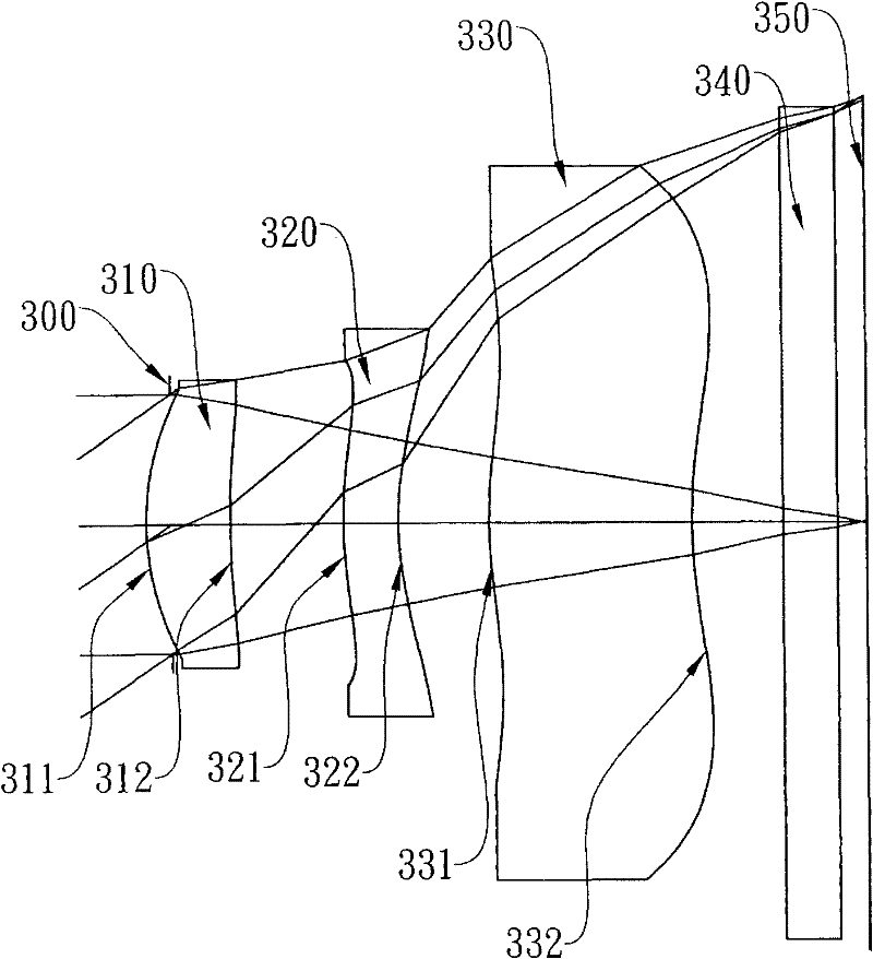
[0125] Please refer to the second embodiment of the present invention image 3 , for the aberration curve of the second embodiment, please refer to Figure 4 . The imaging optical system of the second embodiment is mainly composed of three lenses, which sequentially include from the object side to the image side:
[0126] A first lens 310 with positive refractive power has a convex surface 311 on the object side and a concave surface 312 on the image side, and its material is plastic. Both the object side surface 311 and the image side surface 312 of the first lens 310 are aspherical ;
[0127] A second lens 320 with negative refractive power, the object side surface 321 is convex, the image side surface 322 is concave, and its material is plastic. The object side surface 321 and image side surface 322 of the second lens 320 are both aspherical ;
[0128] A third lens 330 with positive refractive power, the object side surface 331 is convex, the image side surface 332 is c...
no. 3 example 》
[0149] Please refer to the third embodiment of the present invention Figure 5 , for the aberration curve of the third embodiment, please refer to Image 6 . The imaging optical system of the third embodiment is mainly composed of three lenses, which sequentially include from the object side to the image side:
[0150] A first lens 510 with positive refractive power has a convex surface 511 on the object side and a concave surface 512 on the image side, and its material is plastic. Both the object side surface 511 and the image side surface 512 of the first lens 510 are aspherical ;
[0151] A second lens 520 with negative refractive power, the object-side surface 521 is convex, and the image-side surface 522 is concave, and its material is plastic. The object-side surface 521 and image-side surface 522 of the second lens 520 are both aspherical ;
[0152] A third lens 530 with negative refractive power, the object-side surface 531 is convex, the image-side surface 532 is ...
PUM
 Abstract
Description
Claims
Application Information