AI technical title is built by PatSnap AI team. It summarizes the technical point description of the patent document.
一种记录装置、装备的技术,应用在打印装置、印刷等方向
Active Publication Date: 2017-08-29
SEIKO EPSON CORP
View PDF10 Cites 2 Cited by
Summary
Abstract
Description
Claims
Application Information
AI Technical Summary
This helps you quickly interpret patents by identifying the three key elements:
Problems solved by technology
Method used
Benefits of technology
Problems solved by technology
Therefore, when the user replaces the ink recovery tank, it is necessary to perform a burdensome and troublesome work of moving the printer main body from its installation place to a place where the ink recovery tank can be easily replaced.
Method used
Image
Click on the blue label to locate the original text in one second.
Reading with bidirectional positioning of images and text.
Examples
no. 1 Embodiment approach
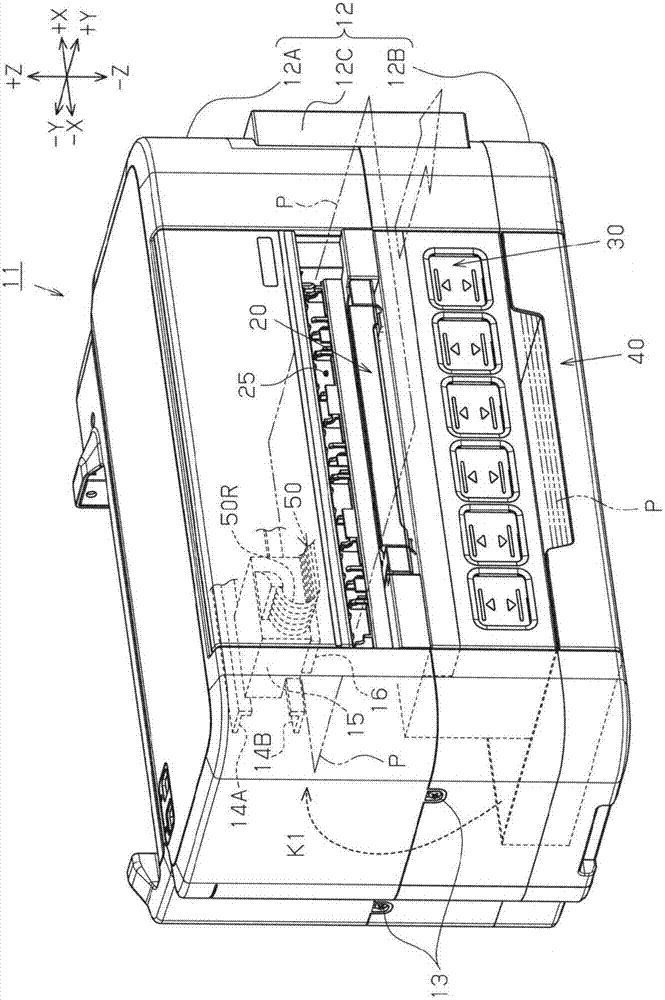
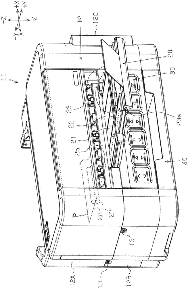
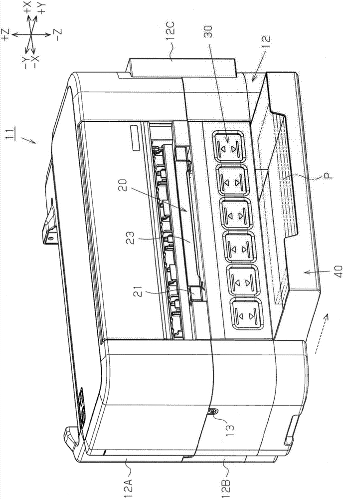
[0060] Such as figure 1 As shown, a printer 11 as an example of a recording device has a printer body 12 having a substantially rectangular parallelepiped shape as the device body. A plurality of cases such as the lower case 12B located on the gravity direction (−Z direction) side and the cover case 12C described later are configured. Furthermore, the housings 12A, 12B, and 12C are connected and fixed to each other by screws 13 or the like. In addition, the printer 11 includes a liquid ejection head 16 , a discharge unit 20 for discharging printing paper P, a liquid container 30 capable of containing ink supplied to the liquid ejection head 16 , and a liquid container 30 capable of containing ink supplied to the liquid ejection head 16 in the printer main body 12 . The supply box 40 of printing paper P.
[0061] The liquid ejection head 16 is located on the side opposite to the gravitational direction (+Z direction) in the vertical direction with respect to the discharge uni...
no. 2 Embodiment approach
[0122] The printer 11 of the second embodiment has a structure in which, in the above-mentioned first embodiment, the liquid recovery unit 60 (liquid storage unit 30 ) is provided below the supply cassette 40 instead of between the discharge unit 20 and the supply cassette 40 . between. A printer 11 according to the second embodiment will be described with reference to the drawings. In addition, in the drawings referred to here, the same reference numerals are assigned to the same components as those of the above-mentioned first embodiment, and description thereof will be omitted.
[0123] Such as Figure 10 As shown, in the printer 11 of the second embodiment, the supply cassette 40 is disposed above the lower casing 12B of the printer main body 12, and the liquid container 30 and the liquid recovery portion 60 overlap the supply cassette 40 in the vertical direction. It is arranged below the supply box 40 (-Z direction) in a manner. Therefore, the storage unit 32 for hous...
no. 3 Embodiment approach
[0129] The printer 11 according to the third embodiment has a configuration in which the liquid recovery unit 60 is provided on the supply cassette 40 in the above-mentioned first embodiment. An example of the third embodiment will be described with reference to the drawings. In addition, in the drawings referred to here, the same reference numerals are assigned to the same components as those of the above-mentioned first embodiment, and description thereof will be omitted.
[0130] Such as Figure 12 As shown, in the printer 11 according to the third embodiment, the supply cartridge 40 is equipped so that it can be inserted and removed with respect to the lower case 12B located on the side of the gravity direction (-Z direction) in the vertical direction, and recovers the liquid from the A liquid recovery unit 60 (housing 61 ) for ink discharged from the ejection head 16 is provided in the supply cartridge 40 .
[0131] In the present embodiment, the liquid recovery unit 60...
PUM
Abstract
There is provided a recording apparatus including a liquid ejecting head that records target ejecting liquid, a discharge unit in which a discharge opening that includes a discharge region, on which recording was performed by the liquid ejecting head, are discharged, is formed, and liquid accommodation units that are capable of accommodating the liquid that is supplied to the liquid ejecting head, the discharge unit being formed from a discharge member towards a discharge direction of a target, the discharge member having a discharge roller discharging the target and a driven roller configured to be opposite to the discharge roller, the liquid accommodation units being arranged in a position below the discharge unit in a perpendicular direction and overlapping with the discharge unit along the perpendicular direction when observed from the direction of discharging the target, a liquid recovery unit being arranged in a position below the discharge unit in the perpendicular direction, in an apparatus main body, a supply box capable of accommodating the target supplied to the liquid ejecting head being equipped below the discharge unit in the perpendicular direction and overlapping with the discharge unit in the perpendicular direction when observed from the direction of discharging the target, and the liquid accommodation units being arranged between the discharge unit and the supply box.
Description
[0001] This application is a divisional application of an invention patent application whose title is "recording device", the application date is November 13, 2014, and the application number is 201410641410.4. technical field [0002] The present invention relates to a recording apparatus that performs recording by ejecting a liquid to an object. Background technique [0003] Conventionally, an inkjet printer is known as one type of recording device, which performs recording (printing) by ejecting ink, which is an example of liquid, from a liquid ejection head onto a target such as printing paper. Furthermore, in such a printer, when performing a relatively large amount of printing, it is required to continuously and stably supply ink to the liquid ejection head. Therefore, a configuration has been proposed in which ink is supplied from an ink cartridge (liquid storage unit) having a relatively large ink storage capacity to a liquid jet head through a liquid supply tube (fo...
Claims
Application Information
Patent Timeline
Application Date:The date an application was filed.
Publication Date:The date a patent or application was officially published.
First Publication Date:The earliest publication date of a patent with the same application number.
Issue Date:Publication date of the patent grant document.
PCT Entry Date:The Entry date of PCT National Phase.
Estimated Expiry Date:The statutory expiry date of a patent right according to the Patent Law, and it is the longest term of protection that the patent right can achieve without the termination of the patent right due to other reasons(Term extension factor has been taken into account ).
Invalid Date:Actual expiry date is based on effective date or publication date of legal transaction data of invalid patent.

