
A foot pedal bracket installation structure

A technology of installation structure and pedals, which is applied in the field of auto parts, can solve the problems of bolts and nuts that are easy to deviate from the initial set position, and poor assembly, etc., to achieve the effect of eliminating poor assembly

Active Publication Date: 2019-12-31
ANHUI JIANGHUAI AUTOMOBILE GRP CORP LTD
View PDF6 Cites 0 Cited by
  • Summary
  • Abstract
  • Description
  • Claims
  • Application Information

AI Technical Summary

Problems solved by technology

[0005] The invention provides a foot pedal bracket installation structure to solve the problems in the prior art that the foot pedal is easily deviated from the initial set position and the bolts or nuts are easy to turn around when the foot pedal is installed on the fuel tank. The bracket installation structure can eliminate the problem of poor assembly caused by the assembly deviation of the fuel tank, and can also solve the problem of the bolts or nuts rotating during assembly when the bolts or nuts are not fixed in advance

Method used

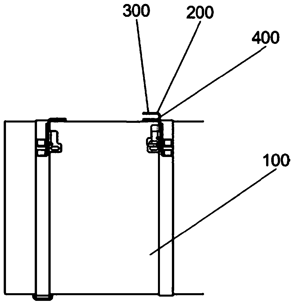
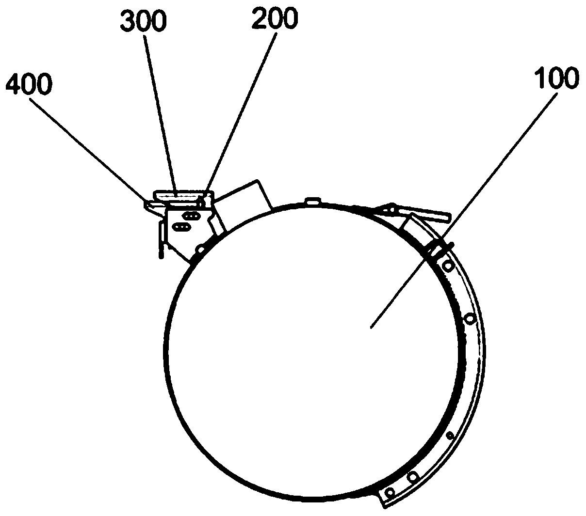

Image

  • A foot pedal bracket installation structure
  • A foot pedal bracket installation structure
  • A foot pedal bracket installation structure

Examples


Embodiment Construction

[0025] The embodiments described below by referring to the figures are exemplary only for explaining the present invention and should not be construed as limiting the present invention.

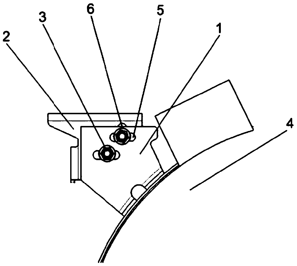
[0026] Such as image 3 As shown, the embodiment of the present invention provides a pedal bracket installation structure, including a first bracket 1, a second bracket 2 and a double-head anti-rotation bolt 3; one end of the first bracket 1 is fixed to the side wall of the fuel tank 4 connected, the other end is connected to the second bracket 2 through the double-headed anti-rotation bolt 3; the first bracket 1 is provided with a first bar-shaped hole 5, and the second bracket 2 is provided with a second bar-shaped hole 6. The double-headed anti-rotation bolt 3 includes a first anti-rotation block 7, a second anti-rotation block 8, a first stud 9 and a second stud 10, and the first stud 9 and the first anti-rotation One side of the rotating block 7 is affixed, the second stud 10 is affixed...


PUM


Abstract

The invention discloses a pedal support mounting structure which comprises a first support, a second support and a double-head anti-rotation bolt. One end of the first support is fixedly connected with the side wall of an oil tank while the other end of the same is connected with the second support through the double-head anti-rotation bolt, the first support is provided with a first strip-shaped hole, a second support is provided with a second strip-shaped hole, the double-head anti-rotation bolt comprises a first anti-rotation block, a second anti-rotation block, a first stud and a second stud, the first stud is fixedly connected with one side of the first anti-rotation block, the second stud is fixedly connected with one side of the second anti-rotation block, the first anti-rotation block is fixedly connected with the second anti-rotation block, width of the first anti-rotation block is equal to that of the first strip-shaped hole, width of the second anti-rotation block is equal to that of the second strip-shaped hole, the first anti-rotation block is connected in the first strip-shaped hole in a clamped manner and can move along axis of the same, and the second anti-rotation block is connected in the second strip-shaped hole in a clamped manner and can move along axis of the same. By the pedal support mounting structure, assembly deviation of a mounting support can be eliminated, and the problem of follow-up rotation of bolts or nuts is solved.

Description

technical field [0001] The invention relates to the technical field of auto parts, in particular to a pedal bracket installation structure. Background technique [0002] The pedal is an important part of the car, mainly used for the driver and passengers to get on and off the car. At the same time, as an important part of the exterior of the vehicle, the pedal needs to cooperate well with the surrounding parts to make the vehicle look good. It looks more coordinated and beautiful. [0003] Due to the high precision of the body itself, it is well matched with the surrounding parts after assembly, and most of the existing pedals are assembled through the mounting bracket on the body. In order to meet the capacity requirements of the fuel tank, the fuel tank needs to extend forward to the lower part of the door. Due to the space limitation between the body and the fuel tank, the pedals can only be installed on the fuel tank. [0004] The existing mode that pedal is installed ...

Claims


Application Information

Patent Timeline
Patent Type & Authority Patents(China)
IPC IPC(8): B60R3/00
CPCB60R3/002
Inventor 周新红阮宇宁李甜甜杨春园张浩
Owner ANHUI JIANGHUAI AUTOMOBILE GRP CORP LTD
Learn More