Electronic fly trap

A fly trap and electronic technology, applied in the field of electric insecticide technology, can solve the problems of high cost, secondary pollution and the like

Inactive Publication Date: 2017-10-03
SHANGHAI BENXING ELECTRONICS TECH
View PDF0 Cites 2 Cited by
  • Summary
  • Abstract
  • Description
  • Claims
  • Application Information

AI Technical Summary

Problems solved by technology

[0006] Fly paper is effective for a single use, and it must be burned after use. Not only is the cost high, but it will also cause secondary pollution

Method used


Image

  • Electronic fly trap
  • Electronic fly trap
  • Electronic fly trap

Examples


Embodiment Construction

[0153] In order to specifically describe an electronic flycatcher of the present invention, the following is further elaborated in conjunction with specific diagrams.

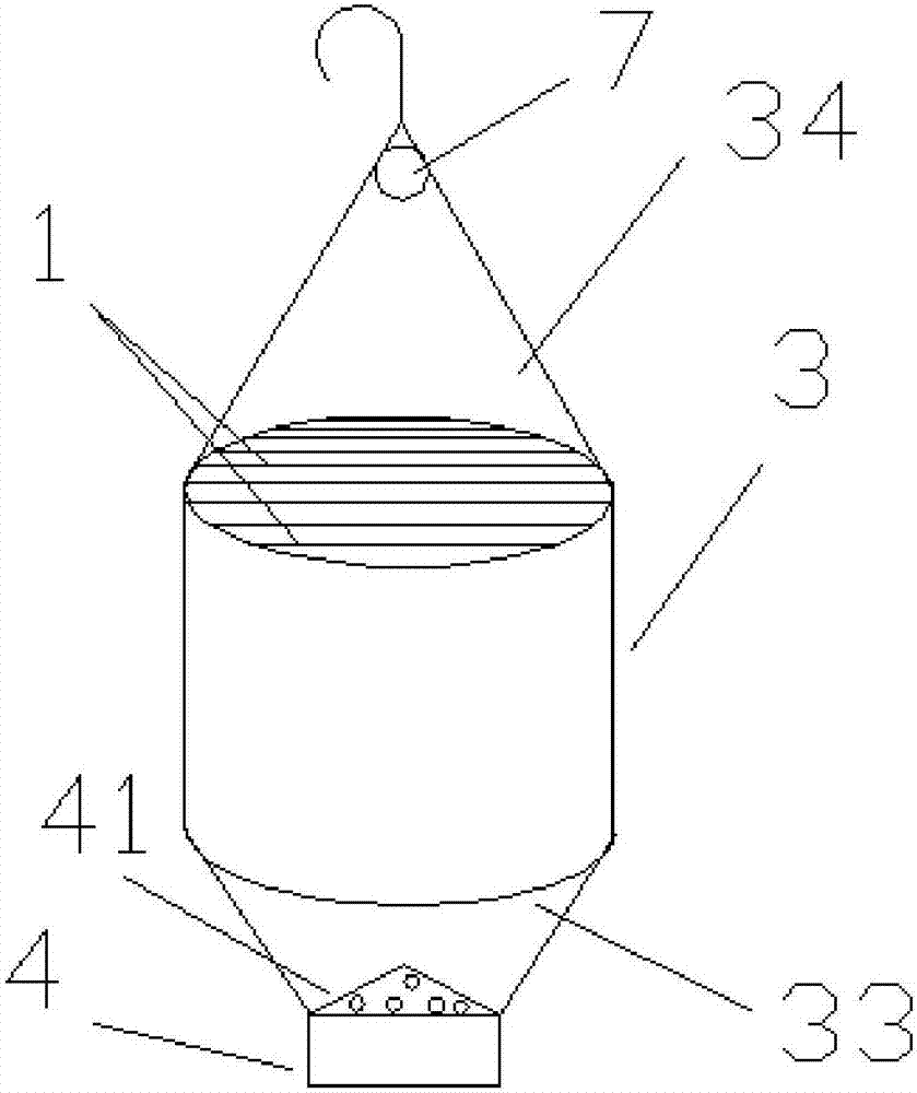
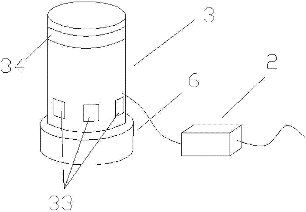
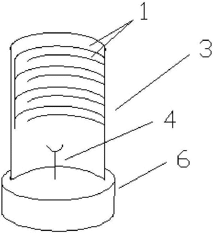
[0154] Reference figure 1 , 2 , 3, 4, 5, electronic fly trap, including a cylinder 3, and a high-pressure insecticidal system. The high-voltage insecticidal system includes a booster module 2 and an insecticidal electrode array 1 connected to the booster module 2. The cylinder 3 is provided with an opening as a fly inlet 33 for flies to fly in. An insecticidal electrode array 1 is provided in the cylinder 3, and the insecticidal electrode array 1 is partially or completely located above the fly inlet 33; the cylinder 3 is provided with a light-transmitting port 34 at least above the middle of the insecticidal electrode array 1. The light port 34 is provided with a transparent window for shielding flies.

[0155] The wall of the cylinder 3 forms a cavity, so that flies cannot fly out of the wall of the cylinder 3. ...


PUM


Abstract

The invention relates to the field of electronics, particularly an electric insect killing technique. The invention provides an electronic fly trap which comprises a cylinder and a high-voltage insect killing system, wherein the high-voltage insect killing system comprises a boosting module and an insect killing electrode array connected with the boosting module; the cylinder is provided with an opening, and the opening is used as a fly inlet through which flies can fly into the cylinder; the insect killing electrode array is arranged in the cylinder, and is partially or wholly positioned above the fly inlet; at least the position of the cylinder above the middle part of the insect killing electrode array is provided with a non-lighttight port; and the non-lighttight port is provided with a transparent window for stopping the flies. After taking off from the bait, the flies can fly to the transparent window above due to the fly-up habit. After being stopped by the transparent window, the flies barge about the cylinder so as to touch the insect killing electrode array and get killed.

Description

Technical field [0001] The invention relates to the field of electronics, in particular to electric insecticidal technology. Background technique [0002] Flies are the first of the four hazards, and are extremely harmful to human production and life. The existing methods of catching flies mainly include spraying pesticides, trapping with fly traps, and sticking with fly paper. [0003] But these methods have many problems. [0004] Spraying pesticides is harmful to humans and animals, and most of the areas hardest hit by flies cannot be used. [0005] Fly traps are only useful for flies that have completed a special flight trajectory, so the efficiency of trapping is low and large-scale flies cannot be trapped. And it needs to be set as a light-transmitting structure, so the dead flies are visible from the outside, which affects the appearance. Fly carcasses in fly traps can also decay and deteriorate, breed bacteria and form bad smells. [0006] Fly paper is effective for a single...

Claims


Application Information

Patent Timeline
Patent Type & Authority Applications(China)
IPC IPC(8): A01M1/02A01M1/04A01M1/22
CPCA01M1/02A01M1/04A01M1/223
Inventor 李兴文
Owner SHANGHAI BENXING ELECTRONICS TECH
Why Eureka
Try Eureka