
Nozzle and soot blower

A technology of soot blower and nozzle, which is applied in the direction of combustion product treatment, combustion method, and removal of solid residue, etc. It can solve the problem of large injection shear force of water wall pipe section, uneven injection of soot blowing surface, wear of water wall pipe section, etc. problems, to reduce the probability of pipe burst hazards, effectively purging dead corners, and reduce pipe wall wear

Active Publication Date: 2017-10-27
CHINA SHENHUA ENERGY CO LTD +2
View PDF9 Cites 1 Cited by
  • Summary
  • Abstract
  • Description
  • Claims
  • Application Information

AI Technical Summary

Problems solved by technology

The nozzles of existing steam soot blowers in power plants generally only spray steam from one nozzle to the furnace. Large, this part of the water-cooled wall pipe section wears more seriously, which is likely to cause a pipe burst accident, resulting in high maintenance costs and potential safety hazards

Method used


Image

  • Nozzle and soot blower
  • Nozzle and soot blower
  • Nozzle and soot blower

Examples


Embodiment Construction

[0025] Specific embodiments of the present invention will be described in detail below in conjunction with the accompanying drawings. It should be understood that the specific embodiments described here are only used to illustrate and explain the present invention, and are not intended to limit the present invention.

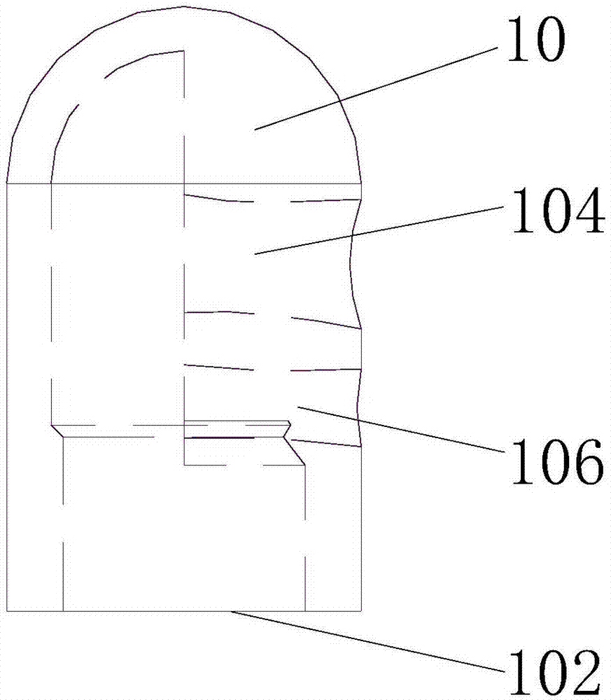
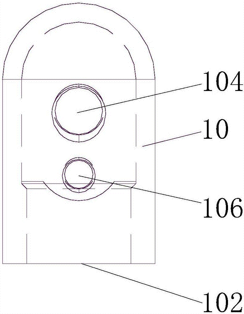
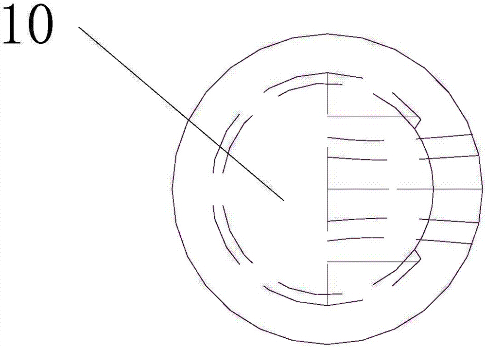
[0026] According to one aspect of the invention, appropriate reference figure 1 , figure 2 and image 3 , the nozzle provided by the present invention includes a hollow body 10, the hollow body 10 has a purge medium inlet 102, and a first nozzle 104 and a second nozzle 106 are sequentially arranged on the side wall of the hollow body 10 along the extending direction of the hollow body 10 , the centerline of the first nozzle 104 and the centerline of the second nozzle 106 are inclined at different angles relative to the cross-section of the hollow body 10 so that the jets of the first nozzle 104 and the second nozzle 106 cross.

[0027] In the above specific ...


PUM


Abstract

The invention relates to the technical field of boiler soot blower equipment, and discloses a nozzle and a soot blower. The nozzle comprises a hollow main body (10), the hollow main body is provided with a blow medium inlet (102), a first nozzle (104) and a second nozzle (106) are arranged in sequence on the side wall of the hollow main body in the hollow main body extension direction, the center line of the first nozzle and the center line of the second nozzle are tilted by different angles relative to the cross section of the hollow main body (10), so that the jet flows of the first nozzle (104) and the second nozzle (106) are crossed. In the technical scheme, the first nozzle and the second nozzle are arranged on the hollow main body, and the center line of the first nozzle and the center line of the second nozzle are tilted by different angles relative to the cross section of the hollow main body, the first nozzle and the second nozzle form a crossing of jet flows, so that the maximum jet shear force on a water wall tube by the jet flows is reduced, and the jet area is enlarged.

Description

technical field [0001] The invention relates to the technical field of boiler soot blowing equipment, in particular to a spray head and a soot blower including the spray head. Background technique [0002] In recent years, with the development of the economy, the power market has become increasingly tense, power construction projects have continued to increase, and unit capacity has continued to increase. Thermal power generation is still the main way to produce electric energy. The boiler of a large thermal power plant is an energy conversion device that converts the chemical energy of coal into heat energy of high-temperature and high-pressure steam. During the operation of the boiler, ash and coking on the heating area are the most common phenomena. The ash layer deposited on the heating surface of the boiler The thermal conductivity is 0.0581-0.116w / ㎡·℃, while the thermal conductivity of the metal pipe wall on the heating surface of the boiler is 46.5-58.1w / ㎡·℃, and the ...

Claims


Application Information

Patent Timeline
Patent Type & Authority Applications(China)
IPC IPC(8): F23J1/00F23J3/00
CPCF23J1/00F23J3/00
Inventor 李延兵卢权郝剑王祖林胡建涛
Owner CHINA SHENHUA ENERGY CO LTD
Learn More