A control method for an axial flow fan with counter-rotating movable blades

A control method and technology for axial flow fans, which are applied in pump control, machine/engine, liquid fuel engine, etc., can solve the problems of deviation from engineering design in pipeline production, increase of fan air volume pressure, and pressure calculation is too conservative, etc., to achieve expansion and high efficiency The effect of operating range, high pressure and compact structure

Active Publication Date: 2019-01-22
ZHEJIANG SHUANGYANG FAN
View PDF7 Cites 1 Cited by
  • Summary
  • Abstract
  • Description
  • Claims
  • Application Information

AI Technical Summary

Problems solved by technology

Thirdly, the calculation of ventilation volume and pressure by ventilation engineers is too conservative. For ventilation engineers, he would rather choose a larger fan power than take the risk of insufficient ventilation due to insufficient fan pressure, because the actual performance of most fans reaches Less than the performance of the label is also one of the reasons that the ventilation engineer greatly increased the air volume pressure of the fan. Third, for the convenience of the pipeline installation and construction personnel, it is common for the pipeline production to deviate from the engineering design. Fourth, as time goes by, many The resistance of the pipeline will change
Seeing this, it is very difficult to greatly improve the actual operating efficiency of the fan to reduce energy consumption by conventional methods

Method used


Image

  • A control method for an axial flow fan with counter-rotating movable blades
  • A control method for an axial flow fan with counter-rotating movable blades
  • A control method for an axial flow fan with counter-rotating movable blades

Examples


Embodiment Construction

[0031] The details of the present invention can be understood more clearly with reference to the accompanying drawings and the description of specific embodiments of the present invention. However, the specific embodiments of the present invention described here are only for the purpose of explaining the present invention, and should not be construed as limiting the present invention in any way. Under the teaching of the present invention, the skilled person can conceive any possible deformation based on the present invention, which should be considered as belonging to the scope of the present invention, and the present invention will be further described below in conjunction with the accompanying drawings.

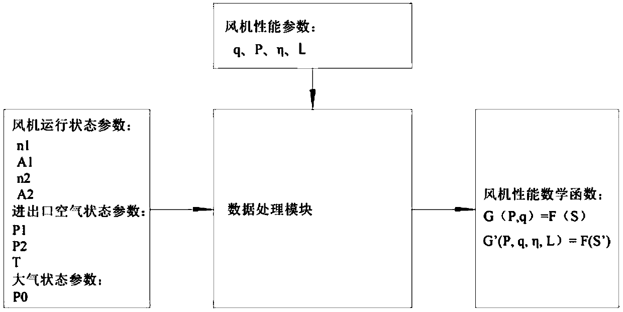
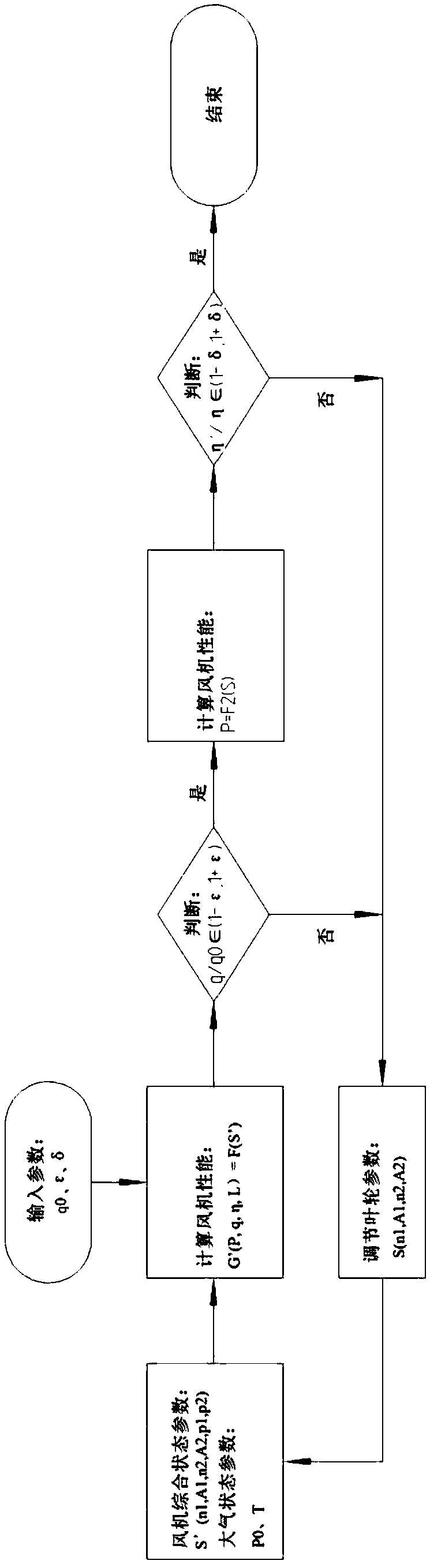
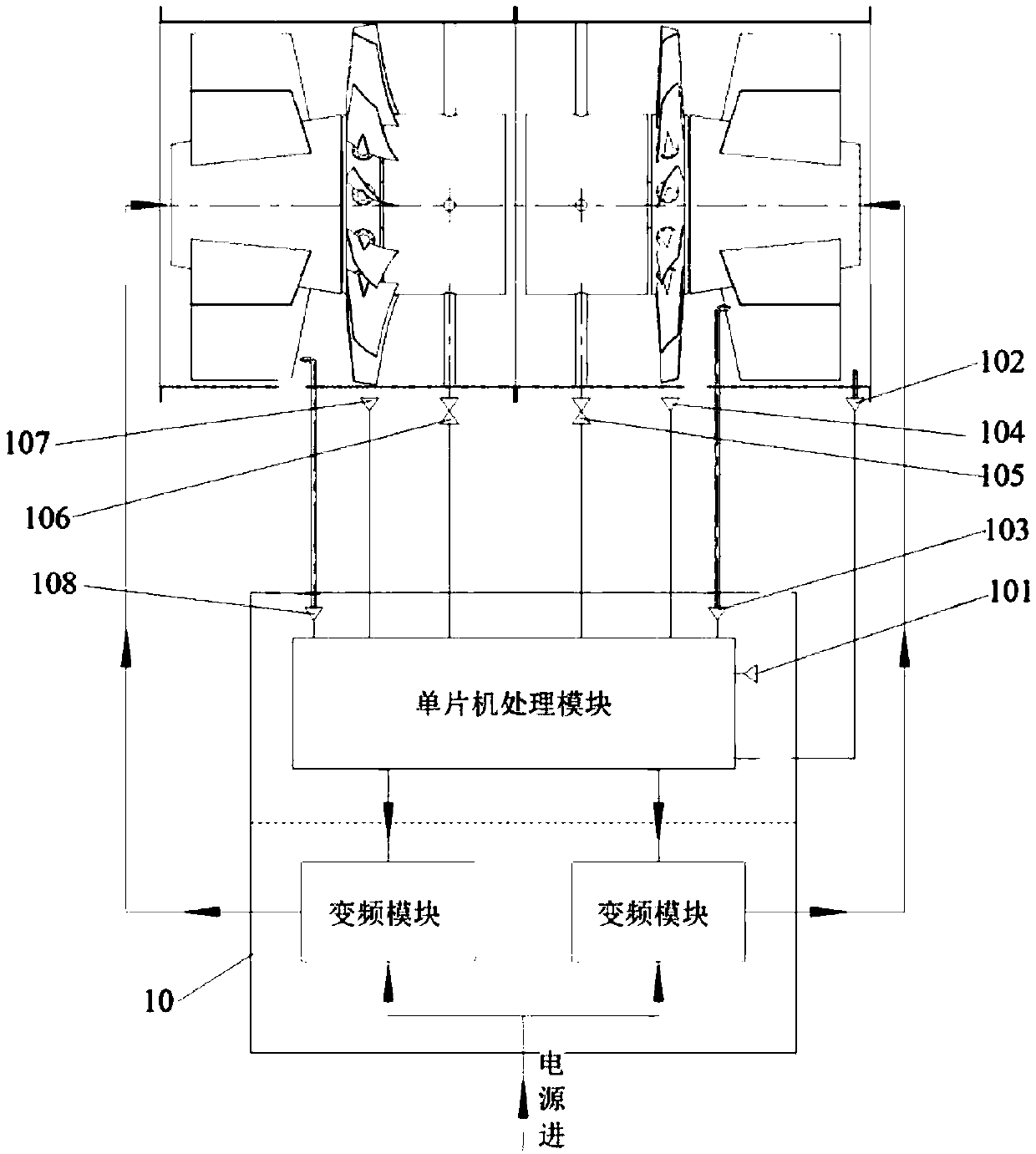
[0032] Figure 1 to Figure 8 They are respectively the flow chart of the first stage of the control method of the present invention, the flow chart of the first stage of the control method of the present invention, the schematic diagram of obtaining the comprehensive stat...


PUM


Abstract

The invention provides a control method for a counter-rotating movable blade adjustable axial flow fan which comprises a first fan unit and a second fan unit. The control method comprises the following steps: acquiring a first function between optimization target performance of a fan and working state parameters of the fan; acquiring a second function between comprehensive performance of the fan and comprehensive state parameters of the fan; obtaining an actual comprehensive state of the fan under a working condition according to the actual working state parameters of the fan under the working condition and the second function; judging whether the actual comprehensive state of the fan meets actual requirements or not, and adjusting the actual working state parameters of the fan until the comprehensive working state of the fan meets the actual requirements if the actual comprehensive state of the fan does not meet the actual requirements; obtaining actual performance of the fan according to the final actual working state parameters of the fan and the first function; judging whether the actual performance of the fan meets the optimal performance state of the fan or not, and adjusting the actual working state parameters of the fan until the actual performance of the fan meets the optimal performance state of the fan if the actual performance of the fan does not meet the optimal performance state of the fan.

Description

technical field [0001] The invention relates to the technical field of fans, in particular to an axial fan with counter-rotating movable blades and adjustable blades. Background technique [0002] According to relevant statistics, the power consumption of pumps and fan loads accounts for more than half of the country's total power generation. This is caused by two factors. link, if used more often, the energy consumption will naturally be large; on the other hand, the performance of pumps and fans is related to the characteristics of the pipeline. With the change of pipeline resistance, the performance of pumps and fans (flow, pressure, power consumption, etc.) It will also change accordingly. Generally, when the blade angle, speed and other parameters are fixed, the efficiency and flow rate change in a parabolic law. There is a highest efficiency point near the design point. Usually, the efficiency of the highest efficiency point is 60% to 80%. However, in practical applic...

Claims


Application Information

Patent Timeline
Patent Type & Authority Patents(China)
IPC IPC(8): F04D27/00F04D29/66
CPCF04D27/00F04D27/002F04D29/66F04D29/666
Inventor 姚大清姚晨蔚董明伟夏爱凤
Owner ZHEJIANG SHUANGYANG FAN
Why Eureka
Try Eureka