
Efficient and energy-saving air overflow dyeing machine with controllable fan airflow

An overflow dyeing machine, high-efficiency and energy-saving technology, applied in the field of air overflow dyeing machine, can solve the problems of air flow function loss, uneven dyeing degree of fabric, air volume not meeting the requirements, etc., to achieve high air pressure and perfect dyeing quality Effect

Pending Publication Date: 2022-05-13
WUXI DONGBAO MACHINERY MFG
View PDF0 Cites 0 Cited by
  • Summary
  • Abstract
  • Description
  • Claims
  • Application Information

AI Technical Summary

Problems solved by technology

[0002] Traditional air overflow dyeing machines are designed with high-power fans equipped with super-large air flow pipes to achieve air flow transmission. This method will cause wind energy loss, wind pressure, and air volume during long-distance travels to fail to meet the requirements, and it takes up a huge space, resulting in If energy consumption and space waste occur, the instructions attached Figure 5 It is a traditional air overflow dyeing machine structure. The air flow pipe at the upper end is guided from one end of the dyeing machine to the top and then connected to the atomization chamber. The ultra-long conveying distance and large-area pipeline design make the air flow function seriously depleted. Figure 5 The fan pipe design of the dyeing machine is designed to supply air for dyeing, which will cause a large amount of energy loss and uneven dyeing of the fabric. Image 6 It is another low-power ductless fan overflow dyeing machine. The airflow entering the atomization chamber cannot be controlled separately. For the dyeing machine with two-pipe channels, single-pipe conversion control cannot be realized.

Method used


Image

  • Efficient and energy-saving air overflow dyeing machine with controllable fan airflow
  • Efficient and energy-saving air overflow dyeing machine with controllable fan airflow
  • Efficient and energy-saving air overflow dyeing machine with controllable fan airflow

Examples


Embodiment Construction

[0020] The following will clearly and completely describe the technical solutions in the embodiments of the present invention. Obviously, the described embodiments are only some of the embodiments of the present invention, rather than all the embodiments. Based on the embodiments of the present invention, all other embodiments obtained by persons of ordinary skill in the art without making creative efforts belong to the protection scope of the present invention.

[0021] see figure 1 , figure 2 , image 3 , Figure 4 , Figure 5 and Figure 6 , the embodiment of the present invention includes:

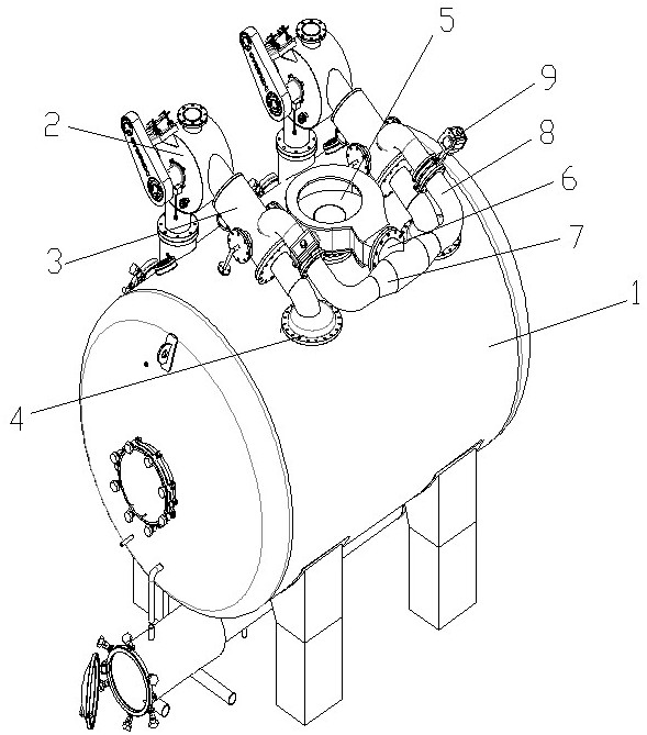
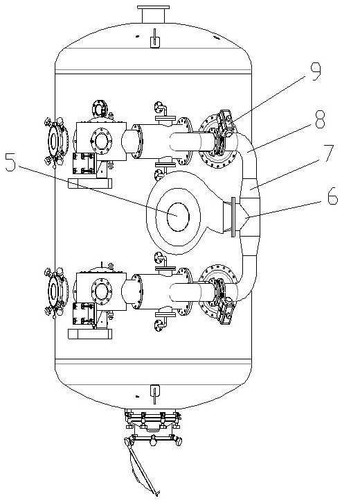
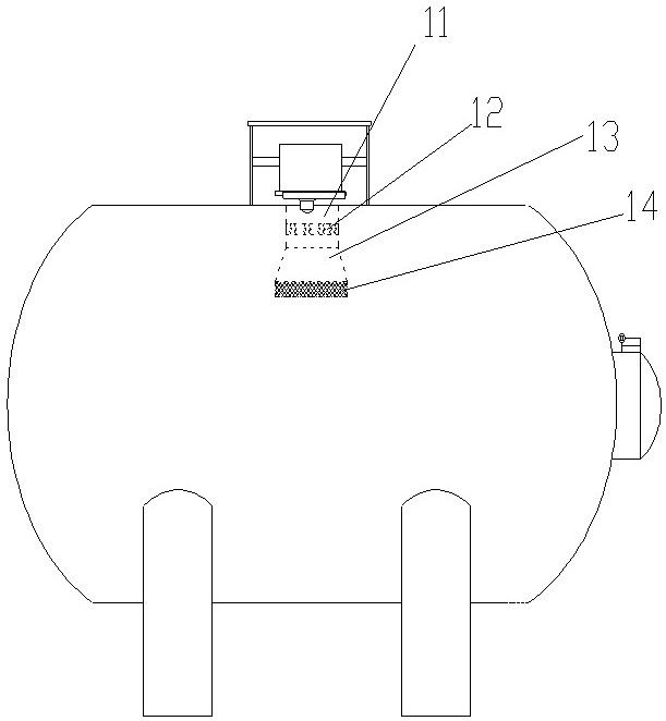
[0022] An air overflow dyeing machine with a high-efficiency and energy-saving fan airflow controllable, comprising a dyeing machine body 1, two sets of cloth lifting wheel devices 2 are fixedly installed on the upper end of the dyeing machine body 1, one end of the cloth lifting wheel device 2 is connected to the The dyeing machine body 1, the other end of the cloth lifting whe...


PUM


Abstract

Two groups of cloth lifting wheel devices are fixedly mounted at the upper end of a dyeing machine body, one end of each cloth lifting wheel device is connected with an upper atomizing chamber, the rear end of each atomizing chamber is connected with a rear cropping seat, and the output end of a main fan is connected with a three-way pipe; a flow dividing device is further installed at the rear position in the air inlet end of the three-way pipe, flow dividing faces are arranged on the two sides of the flow dividing device and face an air outlet of the three-way pipe to divide airflow, the tail end of the slope-crossing taper pipe is connected into the atomizing chamber through airflow pipes, and pneumatic adjusting valves are installed on the airflow pipes. By means of the mode, the main draught fan can be used for carrying out airflow split-flow conveying, the flow speed and flow of airflow can be controlled respectively, high-quality dyeing can be carried out on different fabrics, the layout of a traditional single airflow conveying pipeline is different, the problems that the conveying stroke distance is long and the wind energy loss is large are solved, and high efficiency and energy saving are achieved; the air inlet pipe is provided with the rectifying device so that spiral airflow with larger air volume can be provided, the three-way structure can also provide larger wind energy conveying, and the three-way pipe internally provided with the flow dividing device can avoid the wind energy backflow phenomenon.

Description

technical field [0001] The invention relates to the field of dyeing machines, in particular to an air overflow dyeing machine with controllable air flow of a high-efficiency energy-saving fan. Background technique [0002] Traditional air overflow dyeing machines are designed with high-power fans equipped with super-large air flow pipes to achieve air flow transmission. This method will cause wind energy loss, wind pressure, and air volume during long-distance travel to fail to meet the requirements, and it takes up a huge space, resulting in If energy consumption and space waste occur, the instructions attached Figure 5 It is a traditional air overflow dyeing machine structure. The air flow pipe at the upper end is guided from one end of the dyeing machine to the top and then connected to the atomization chamber. The ultra-long conveying distance and large-area pipeline design make the air flow function seriously lost. Figure 5 The fan pipe design of the dyeing machine is ...

Claims


Application Information

Patent Timeline
Patent Type & Authority Applications(China)
IPC IPC(8): D06B3/28D06B23/20
CPCD06B3/28D06B23/20D06B2700/36
Inventor 潘加龙奚伟民
Owner WUXI DONGBAO MACHINERY MFG
Learn More