
Whole-pneumatic air burst fire extinguishing bomb

An aerial explosion and all-pneumatic technology, which is applied in the field of fire extinguishing bombs, can solve the problems of blowing out the bottle cork, not being able to automatically realize the rotation and start of the control piece, and not being able to be used in simple combination, so as to achieve high throwing accuracy, convenient mobility, and easy use Effect

Inactive Publication Date: 2010-09-29
XIAMEN UNIV
View PDF7 Cites 14 Cited by
  • Summary
  • Abstract
  • Description
  • Claims
  • Application Information

AI Technical Summary

Problems solved by technology

[0006] However, the two cannot be used in simple combination at present, because the pneumatic fireworks shell cannot automatically rotate and start the control piece during the ejection process, so that the sealed high-pressure air cannot blow out the bottle stopper after the automatic delay, and spread the fire in the air. agent

Method used


Image

  • Whole-pneumatic air burst fire extinguishing bomb
  • Whole-pneumatic air burst fire extinguishing bomb
  • Whole-pneumatic air burst fire extinguishing bomb

Examples


Embodiment 1

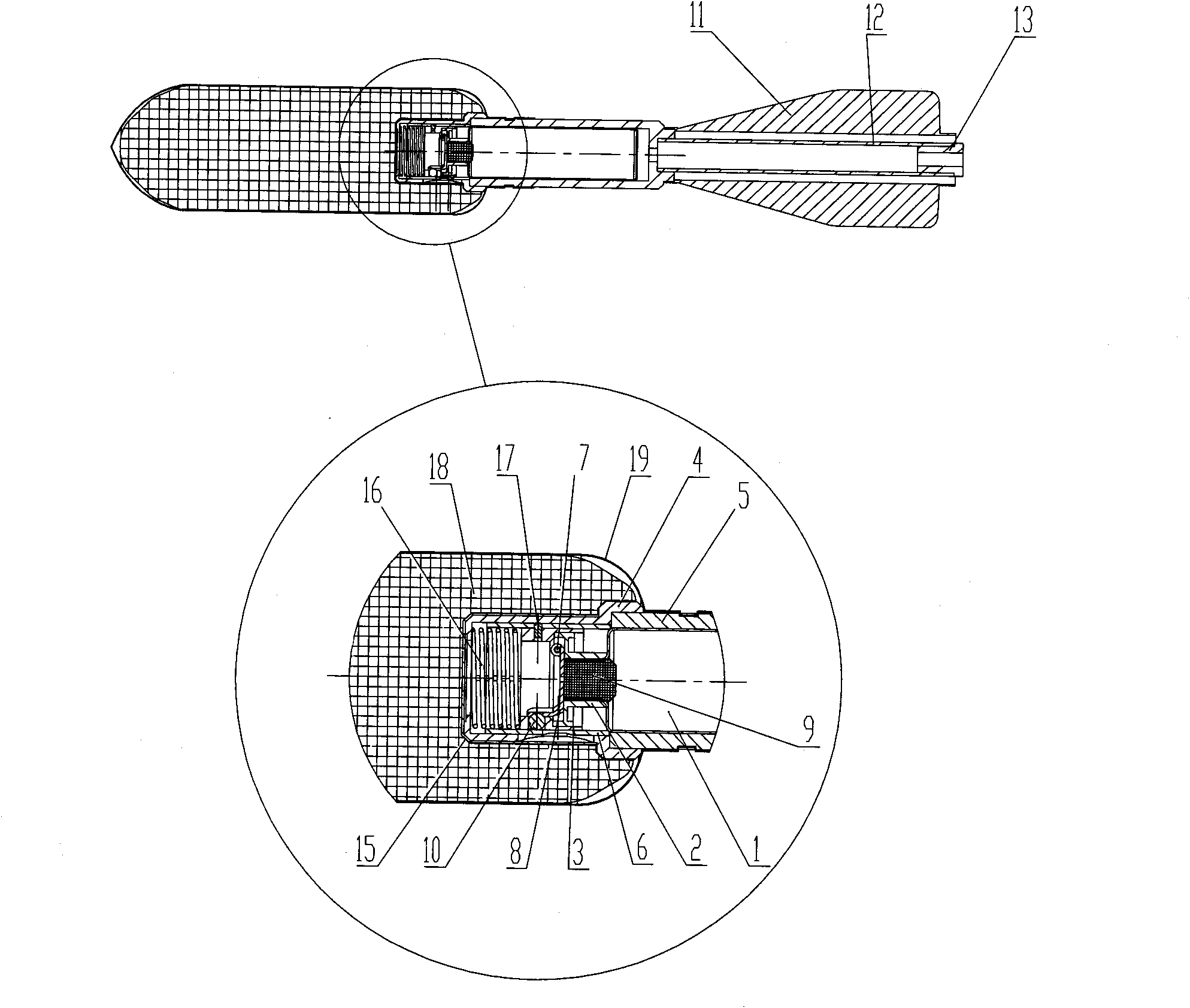
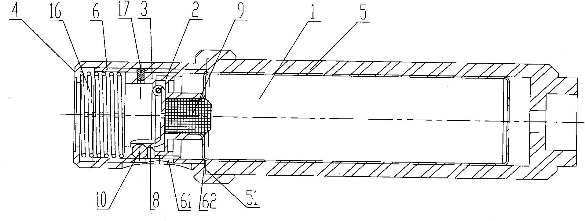
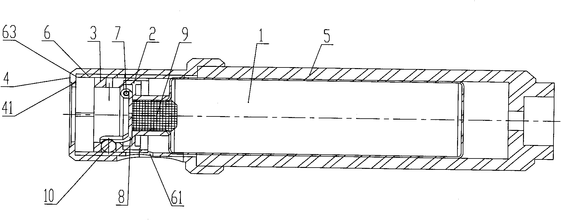
[0037] Such as figure 1 As shown, the all-pneumatic air explosion fire extinguishing bomb is equipped with high-pressure gas cylinder 1, stopper 9, gas cylinder fixing part 2, control piece 8, shaft 7, steel ball 10, starter 3, control sleeve 6, and shear pin 17. , Spring 16, delayed detonator shell 4, gas cylinder shell 5, push tube 12, tail cover 13, tail wing 11, fire extinguishing agent 18 and cartridge case 19, etc.

[0038] Such as figure 2 As shown, in standby, the starter 3 and the control sleeve 6 are connected as a whole through the shear pin 17. Under the action of the pre-compression force of the spring 16, the end surface 62 of the control sleeve 6 abuts against the end 51 of the gas cylinder sleeve 5. , In a safe state to be used. At this time, the starter 3 and the corresponding shear pin 17 holes of the control sleeve 6 are coaxial, and the steel ball sliding hole 61 opened on the control sleeve 6 deviates to the side of the high-pressure gas cylinder 1 relative ...

Embodiment 2

[0042] Example 2, such as Figure 5 As shown, it is similar to Embodiment 1, and the difference is that when the fire extinguishing bomb is launched by high-pressure gas, the launched high-pressure gas applies force to the bottom of the high-pressure gas cylinder 1 through the push rod 14, thereby controlling the high pressure in the projectile. When the air is delayed for detonation, the push rod 14 cooperates with the push tube 12. In the standby position, the force end of the push rod 14 is lower than the end surface of the tail cover 13 to prevent accidental triggering.


PUM


Abstract

The invention discloses a whole-pneumatic air burst fire extinguishing bomb relating to a fire extinguishing bomb, and provides an air burst fire extinguishing bomb with flexible and light use. The whole-pneumatic air burst fire extinguishing bomb is provided with a gas cylinder, a bottle stopper, a gas cylinder solid joint piece, a control sheet, an axle, a steel ball, a starting piece, a control sleeve, a shearing pin, a spring, a delay electric detonator case, a sheath, a gas cylinder case, an ejector sleeve and a tail hood, wherein the gas cylinder solid joint piece is fixedly connected with the gas cylinder and is provided with an axle hole which is matched with the axle; the control sheet supports and tightly presses the bottle stopper by the axle and the steel ball; high-pressure air is injected into the gas cylinder by the bottle stopper in advance; the starting piece is fixedly connected with the cylinder solid joint piece; the front part of the starting piece contacts with the spring; the delay electric detonator case is connected with the gas cylinder case; the starting piece is connected with a control sleeve by the shearing pin; the shearing pins corresponding to the starting piece and the control sleeve are concentric; a steel ball sliding-out hole arranged on the control sleeve deviates to the gas cylinder relatively to the starting piece steel hole; the ejector sleeve is arranged behind the gas cylinder; and the tail cover is arranged on the tail part of the ejector sleeve.

Description

Technical field [0001] The invention relates to a fire-extinguishing bomb, in particular to a fully pneumatic air-explosive fire-extinguishing bomb which is mainly suitable for tree crown fire fighting. Background technique [0002] After a mountain forest is on fire, the forest fire usually spreads through the canopy to neighboring trees, so extinguishing the canopy flame is usually the key to extinguishing the forest fire. In order to extinguish the canopy flames, it is best to use airplanes to extinguish fires from the air. However, the use of airplanes to extinguish fires usually has a slower reaction speed and higher cost, and is generally only suitable for large forest areas. For hilly areas, the forest area is not large. When the scale of the fire is not large, it is obviously not appropriate to use aircraft to extinguish the fire. If the aircraft is not used to extinguish the fire, the existing technical means are mainly to open up isolation belts, or use fire extinguishe...

Claims


Application Information

Patent Timeline
Patent Type & Authority Applications(China)
IPC IPC(8): A62C19/00F42B12/46
Inventor 周军现张建寰
Owner XIAMEN UNIV
Learn More