Electric energy emission structure and wireless charging device employing same

A technology of transmitting coil and electric energy, applied in circuit devices, electrical components, etc., can solve the problems of increasing the voltage at both ends of the transmitting coil, increasing the EMC radiation interference, increasing the EMC conduction interference, etc., so as to reduce the EMC radiation interference and reduce the high frequency common Mode current, reducing the effect of EMC conduction interference

Inactive Publication Date: 2017-11-10
NINGBO WEIE ELECTRONICS TECH CO LTD
View PDF2 Cites 1 Cited by
  • Summary
  • Abstract
  • Description
  • Claims
  • Application Information

AI Technical Summary

Problems solved by technology

like figure 2 As shown, the high-frequency AC voltage on the coil is more likely to form a common-mode current to the ground through this parasitic capacitance, which increases EMC conduction interference
Moreover, when the size of the transmitting coil increases, the circumference of the coil will increase accordingly. If a high-frequency alternating current flows through the coil, then the high-frequency current is more likely to form electromagnetic waves to radiate out, increasing EMC radiation interference
[0004] Another way is to increase the magnetic field of the transmitting coil by increasing the alternating current in the transmitting coil, which will increase the voltage at both ends of the transmitting coil (V=jωLs·Is), according to the calculation formula of the above-mentioned common mode current, also will increase the common mode current to ground

Method used


Image

  • Electric energy emission structure and wireless charging device employing same
  • Electric energy emission structure and wireless charging device employing same
  • Electric energy emission structure and wireless charging device employing same

Examples


Embodiment Construction

[0029] Some preferred embodiments of the present invention will be described in detail below with reference to the accompanying drawings, but the present invention is not limited thereto.

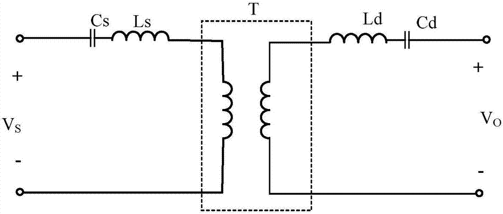
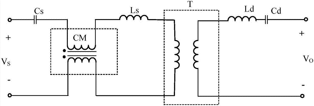
[0030] refer to image 3 The wireless charging device shown, the wireless charging device includes a power transmitting end (that is, a power transmitting structure) and a power receiving end, the power transmitting end includes an inverter circuit (not shown), a power transmitting coil Ls, the The inverter circuit receives an external DC voltage signal to output an AC voltage signal Vs. Further, the power transmitting end further includes a common-mode current suppression circuit. In this embodiment, the common-mode current suppression circuit specifically includes a common-mode inductor CM. The power receiving end includes a resonant capacitor Cd and a power receiving coil Ld. The wireless charging device also includes a transformer T.

[0031] In this embodiment, in order to achieve h...


PUM


Abstract

The invention discloses an electric energy emission structure and a wireless charging device employing the same. By connecting a common-mode current suppression circuit between an inversion circuit and an emission coil, a common-mode current between the emission coil and the ground can be reduced very well, the conduction interference of electromagnetic compatibility (EMC) is reduced, meanwhile, a high-frequency common-mode current generated by a high-frequency component of an AC voltage output from the inversion circuit on the emission coil also can be reduced, and the radiation interference influence of the high-frequency AC component on the EMC of a system is reduced.

Description

technical field [0001] The invention relates to the field of wireless charging, in particular to an electric energy transmitting structure and a wireless charging device using the same. Background technique [0002] The magnetic resonance wireless charging system includes a power transmitter and a power receiver, such as figure 1 As shown, the power transmitter receives external power to generate a spatial magnetic field to wirelessly transmit the energy to the power receiver. [0003] In order to enable the power receiving end to induce a spatial magnetic field in a wider range to generate voltage for electronic equipment, one way is to increase the size and inductance of the transmitting coil in the power transmitting end, but increase the size and inductance of the transmitting coil, It is often necessary to increase the number of turns and area of ​​the transmitting coil, and according to the calculation formula of capacitance, C=εS / D, increasing the coil area will incr...

Claims


Application Information

Patent Timeline
Patent Type & Authority Applications(China)
IPC IPC(8): H02J50/12
Inventor 车丙晨
Owner NINGBO WEIE ELECTRONICS TECH CO LTD
Why Eureka
Try Eureka