Electromagnet drive control circuit of heating electric appliance and heating electric appliance
A technology for driving control circuits and heating appliances. It is applied in the direction of electrical components and electric heating devices. It can solve problems such as low voltage at both ends of the coil, non-working toaster, electromagnetic noise pollution, etc., to reduce the opening speed, optimize the rising slope, The effect of extending the rising edge time
- Summary
- Abstract
- Description
- Claims
- Application Information
AI Technical Summary
Problems solved by technology
Method used
Image
Examples
no. 1 example
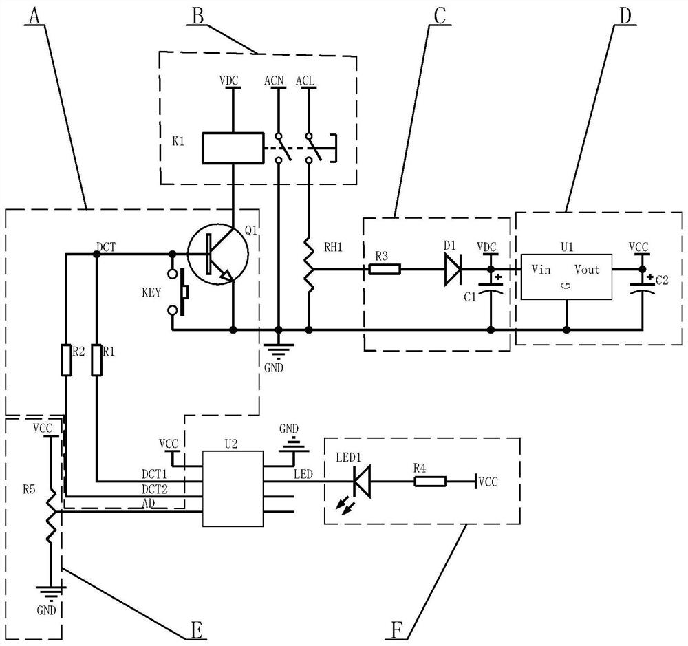
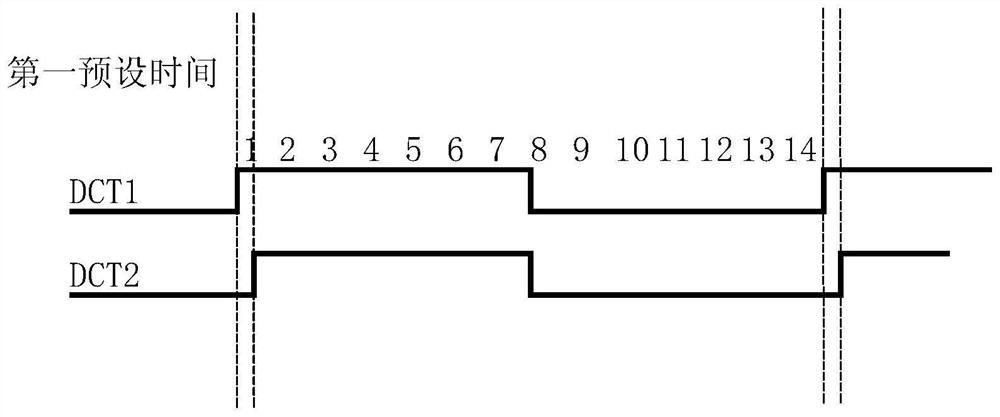
[0026] see Figure 1-Figure 2 , the electromagnet drive control circuit of the heating appliance, taking a toaster as an example, includes an electromagnet drive module A, an electromagnet switch module B, a timing circuit module E, an indicator light module F, an electromagnet power supply module C, and a control chip power supply Module D and the control chip U2, the control chip U2 is respectively connected to the electromagnet drive module A, the timing circuit module E and the indicator light module F, the electromagnet drive module A is connected to the electromagnet switch module B, and the electromagnet switch module B is used to control the mains The electromagnet power supply module C is connected between the mains and the control chip power supply module D. The electromagnet power supply module C is used to provide electric energy to the electromagnet switch module B, and the control chip power supply module D is used to provide power to the control chip U2. Electri...
no. 2 example
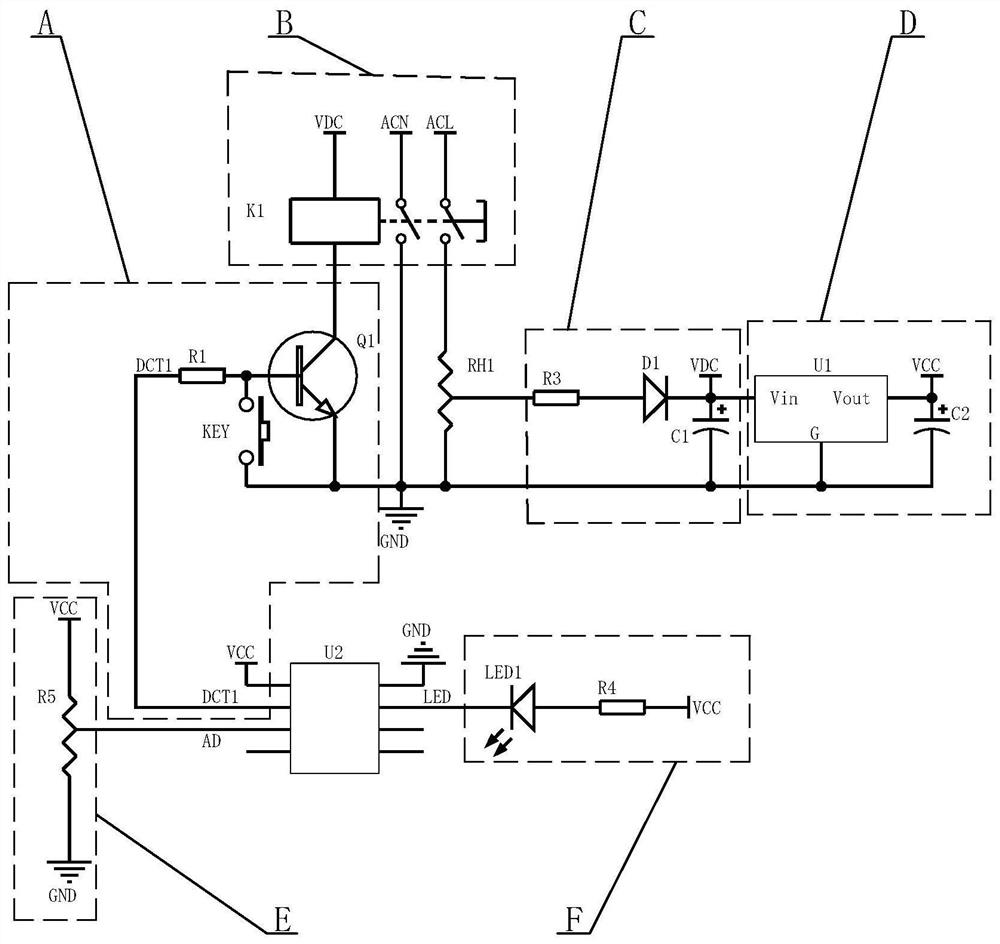
[0037] see Figure 3-Figure 4 , the electromagnet drive control circuit of the heating appliance, taking the toaster as an example, it is different from the first embodiment in that:
[0038] The electromagnet drive module A includes a resistor R1, a transistor Q1 and a button KEY, the first control signal output port DCT1 of the control chip U2 is connected to one end of the resistor R1, and the other end of the resistor R1 and the first end of the button KEY are connected to the transistor Q1 The base (B pole) of the button KEY is grounded, and the inside of the control chip U2 (single-chip microcomputer) is provided with a pull-up resistor, and the resistance value of the resistor R1 is smaller than the resistance value of the pull-up resistor.
[0039] In one cycle, when the electromagnet K1 is in the closed state, first set the first control signal output port DCT1 of the control chip U2 to the input state or the open-drain output state (open-drain means that there is no ...
PUM
 Abstract
Description
Claims
Application Information
 - R&D
- Intellectual Property
- Life Sciences
- Materials
- Tech Scout
- Unparalleled Data Quality
- Higher Quality Content
- 60% Fewer Hallucinations
Browse by: Latest US Patents, China's latest patents, Technical Efficacy Thesaurus, Application Domain, Technology Topic, Popular Technical Reports.
© 2025 PatSnap. All rights reserved.Legal|Privacy policy|Modern Slavery Act Transparency Statement|Sitemap|About US| Contact US: help@patsnap.com


