Sludge treatment device having dehydrator

A technology of sludge treatment and dehydrator, which is applied in the direction of sludge treatment, sludge treatment, dehydration/drying/thickened sludge treatment, etc. It can solve the problem of reducing sludge volume, shorten operation time and increase sludge treatment The effect of reducing the amount and shortening the discharge time

Inactive Publication Date: 2015-11-04
大韩环境科技株式会社
View PDF6 Cites 8 Cited by
  • Summary
  • Abstract
  • Description
  • Claims
  • Application Information

AI Technical Summary

Problems solved by technology

Therefore, the amount of sludge that can be treated by the existing sludge treatment equi

Method used


Image

  • Sludge treatment device having dehydrator
  • Sludge treatment device having dehydrator
  • Sludge treatment device having dehydrator

Examples


Example Embodiment

[0024] Hereinafter, embodiments of the present invention will be described in detail with reference to the accompanying drawings to facilitate implementation by those skilled in the art. However, the present invention can be embodied in various different forms and is not limited to the following embodiments.

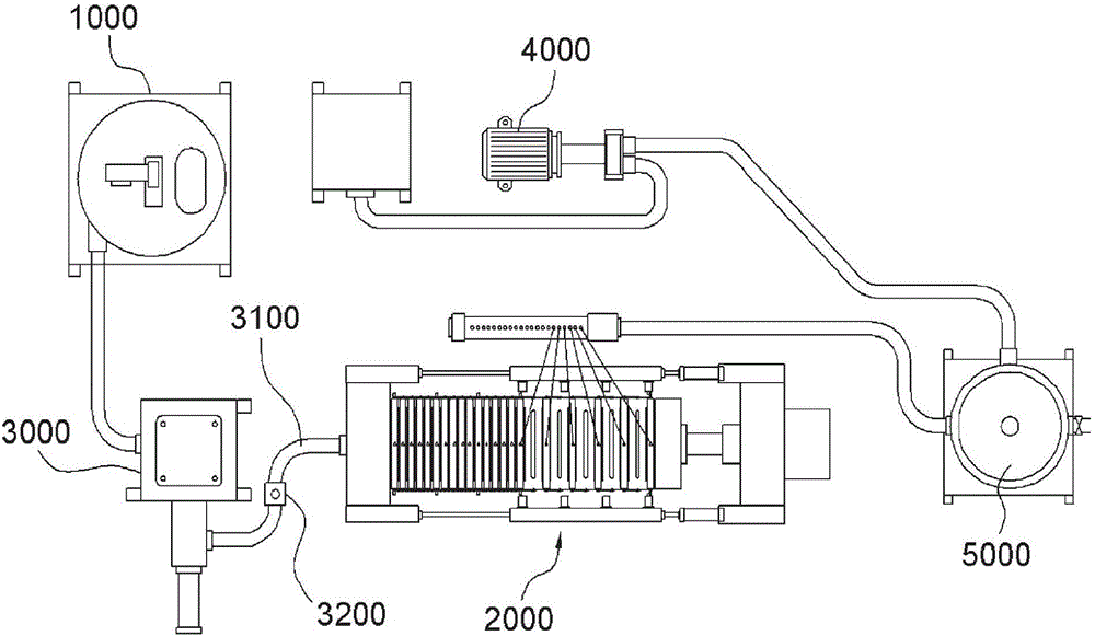
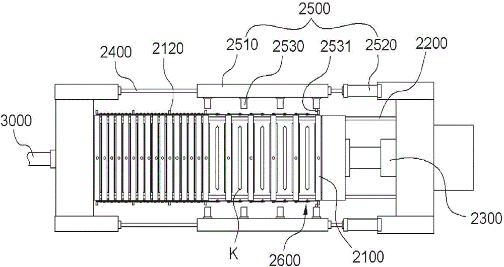
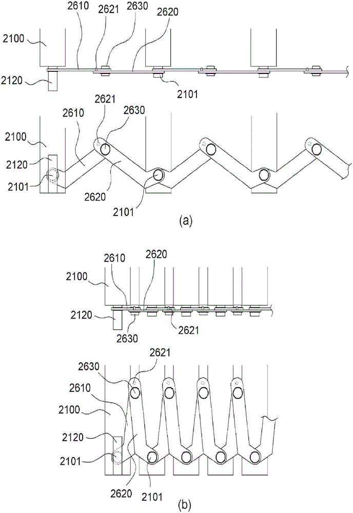
[0025] figure 1 It is a schematic diagram of the overall system of the sludge treatment device equipped with a dehydrator of the present invention, figure 2 Is a schematic plan view of the dehydrator of the present invention, image 3 Is a schematic cross-sectional view of the dewatering plate provided on the dewatering device of the present invention, Figure 4 It is the action state diagram of the connecting rod and the driving sequence of the connecting rod of the present invention, Figure 5 It is a schematic front view of the dehydration plate provided on the dehydrator of the present invention, Image 6 It is a schematic plan view of the sequence in which the dewateri...


PUM


Abstract

The present invention relates to a sludge treatment device in which sludge is inserted into a dehydrating plate and is pressed with high pressure by a hydraulic cylinder such that a filtrate of a liquid state is discharged and, more specifically, to a sludge treatment device having a dehydrator, the sludge treatment device comprising: a heat water pipe having high-temperature hot water circulated therein, and formed on a dehydrating plate coming into contact with sludge such that dehydration performance can be improved; and a moisture content measurement sensor provided inside the dehydrating plate such that the content of moisture of a dehydrating cake can be adjusted and the dehydrating cake can be automatically discharged.

Description

technical field [0001] The present invention relates to a sludge treatment device that discharges liquid filtrate through high-pressure compression of a hydraulic cylinder when sludge is put into a dewatering plate. A sludge treatment device equipped with a dehydrator that not only adjusts the water content but also automatically discharges dewatered cakes by installing a water content detection sensor in the dehydration plate to improve dehydration performance. Background technique [0002] Generally, a sludge treatment device refers to a device that presses physically or chemically treated colloidal sludge (sludge) into a plurality of filter plates formed with a filter membrane under high pressure for the purpose of post-treatment in the sewage treatment process. The multiple filter plates that flow into the sludge are compressed by a hydraulic device, and the filtrate filtered through the filter membrane is discharged to the outside, and the filter plates are opened by a ...

Claims


Application Information

Patent Timeline
IPC IPC(8): C02F11/12B01D33/04C02F11/122C02F11/13
CPCC02F11/121B01D25/164B01D25/172B01D25/215B01D25/386C02F3/006C02F11/18C02F11/122C02F11/13Y02W10/20C02F2201/002B01D25/287C02F11/15B01D25/003C02F2301/063C02F2209/00C02F2209/02
Inventor 韩俊熙
Owner 大韩环境科技株式会社
Why Eureka
Try Eureka