Anti-static protective circuit for luminous tube

A technology for protecting circuits and luminous tubes, applied in the direction of static electricity, circuits, electrical components, etc., can solve problems affecting the use of luminous tubes, and achieve the effects of preventing breakdown and reducing discharge time

Inactive Publication Date: 2005-03-02
BEIJING TIMESLED TECH CO LTD
View PDF0 Cites 9 Cited by
  • Summary
  • Abstract
  • Description
  • Claims
  • Application Information

AI Technical Summary

Problems solved by technology

The above situation has seriously affected the use of luminous tubes

Method used


Image

  • Anti-static protective circuit for luminous tube
  • Anti-static protective circuit for luminous tube
  • Anti-static protective circuit for luminous tube

Examples


Embodiment Construction

[0014] The present invention will be further described below in conjunction with the accompanying drawings and specific embodiments.

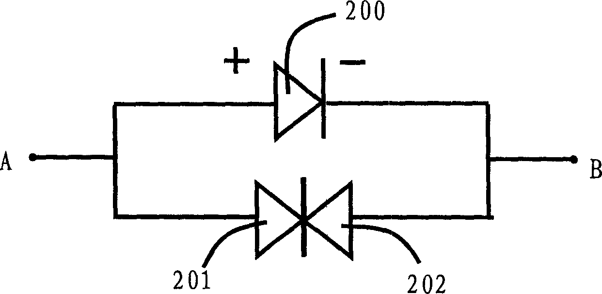
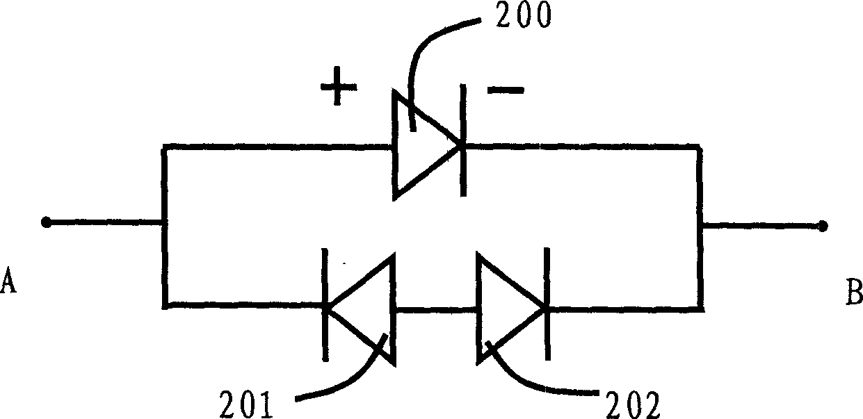
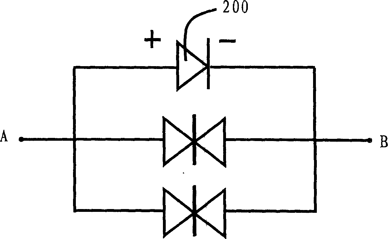
[0015] figure 1 It is a specific embodiment of the antistatic protection circuit of the present invention. Connect the negative pole of the diode 201 to the negative pole of the diode 202, connect the positive pole of the diode 201 to the positive pole of the protected light-emitting tube 200 and lead out the electrode A, and connect the diode 202 The positive pole of the protected luminous tube 200 is connected to the negative pole of the protected luminescent tube 200 and leads to electrode B. In this way, the diode 201 and the diode 202 are connected in series to protect the light emitting tube 200 . Similarly, the antistatic protection circuit of the present invention can also adopt the form that two anodes of two diodes are interconnected, and the cathodes are respectively connected to the two ends of the luminous tube to be protected. ...


PUM


Abstract

This invention relates to an antistatic protection circuit used in a luminetron which installs in parallel a set of serial butt joint diodes with the luminotron in the circuit, the diodes can be either negatively or positively inter-connected. When their negatives are inter-connected, the positives are connected with both poles of the luminotron, when their positives are interconnected, the negatives are connected with both poles of the luminotron. The reversed blackout voltage should be less than that of the luminotron and larger than that of the forward working voltage. A set of serial opposite-joint diodes can be formed by two or many diodes to form antistatic protection circuit which can be made up of isolated components or semicondutor integration.

Description

technical field [0001] The invention relates to an antistatic protection circuit of a light-emitting tube, in particular to a group of series-connected diode circuits, belonging to the technical field of semiconductor optoelectronics. Background technique [0002] Light-emitting tubes have a wide range of application requirements in transportation, display, automobile, lighting and other fields. In most applications, the light-emitting tube mainly works in the circuit in the form of multiple devices connected in series. If one of the light-emitting tubes is damaged due to the action of electrostatic pulses, the circuit in which multiple light-emitting tubes are connected in series will fail; The circuit connected in parallel with the light-emitting tube to protect against static electricity has a slow discharge speed and lacks self-protection ability due to the existence of junction capacitance, and at the same time, unnecessary power consumption is caused by the existence o...

Claims


Application Information

Patent Timeline
Patent Type & Authority Applications(China)
IPC IPC(8): H01L23/60H05F3/00
Inventor 邹德恕沈光地张剑铭郭霞王新潮董立闽
Owner BEIJING TIMESLED TECH CO LTD
Why Eureka
Try Eureka