Power cable partial discharge positioning method based on time reversal

A power cable and partial discharge technology, applied in the direction of measuring electricity, measuring electrical variables, testing dielectric strength, etc., can solve the problem of low positioning accuracy and achieve the effect of improving positioning accuracy and precise positioning

Active Publication Date: 2017-11-24
SICHUAN UNIV
View PDF8 Cites 19 Cited by
  • Summary
  • Abstract
  • Description
  • Claims
  • Application Information

AI Technical Summary

Problems solved by technology

[0005] Aiming at the problem that the positioning accuracy of the current power cable partial discharge location method is not high, the purpose of the present invent...

Method used


Image

  • Power cable partial discharge positioning method based on time reversal
  • Power cable partial discharge positioning method based on time reversal
  • Power cable partial discharge positioning method based on time reversal

Examples


Embodiment 1

[0043] The power cable tested in this embodiment is the partial discharge location of the 498m ZR-YJV22-8.7 / 15 power cable, and the defect type of the power cable is a defect of poor lapping of the semiconductive layer.

[0044] In this embodiment, an Agilent E5061B network tester is used to test the transfer function of the reference power cable.

[0045] In this embodiment, the partial discharge test of the power cable under test is carried out by using the OWTS HV250 oscillating wave partial discharge test system of Germany Saiba.

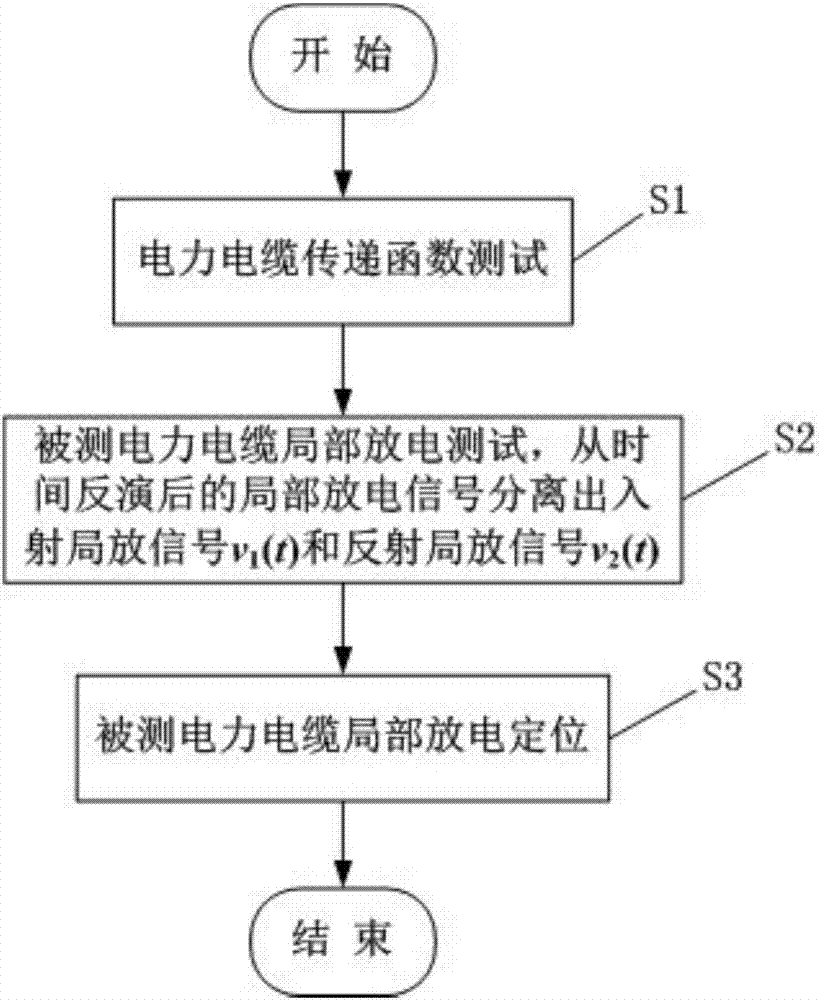
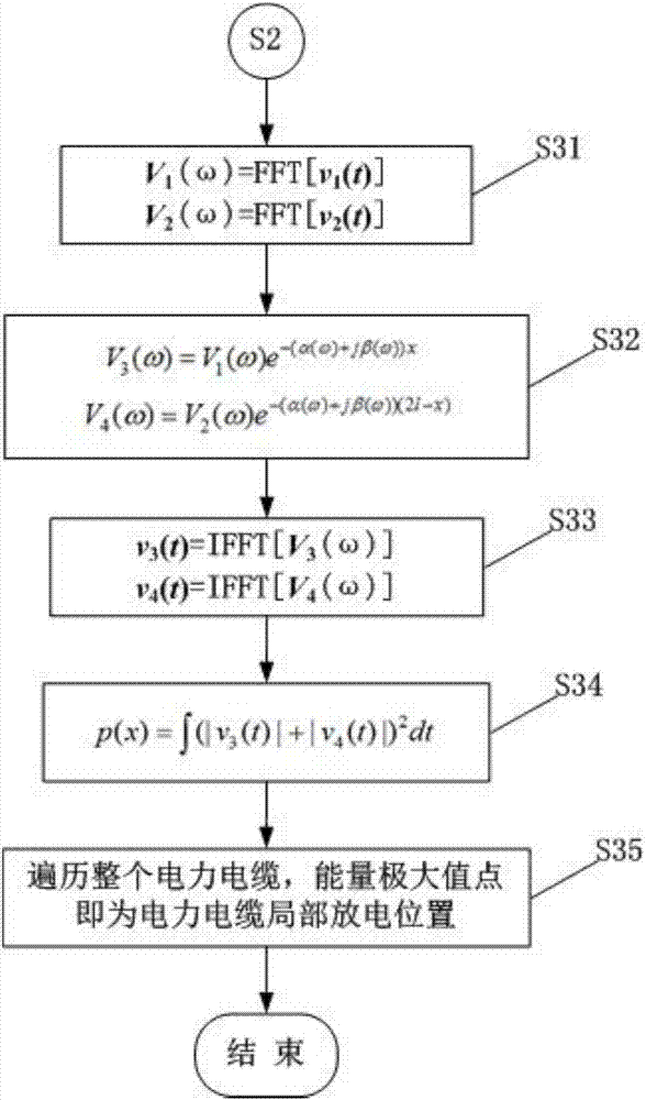
[0046] The method for locating partial discharges in power cables based on time inversion provided in this embodiment, such as figure 1 and figure 2 shown, including the following steps:

[0047] S1 power cable transfer function test

[0048] The length of the same model and batch as the power cable under test is l 0 The two ends of the 10-meter reference power cable are respectively connected to the signal output end and signal receiving e...

Embodiment 2

[0067] The power cable tested in this embodiment is the partial discharge location of the 498m ZR-YJV22-8.7 / 15 power cable, and the defect type of the power cable is a longitudinal knife mark defect.

[0068] In this embodiment, an Agilent E5061B network tester is used to test the transfer function of the reference power cable.

[0069] In this embodiment, the partial discharge test of the power cable under test is carried out by using the OWTS HV250 oscillating wave partial discharge test system of Germany Saiba.

[0070] The method for locating partial discharges in power cables based on time inversion provided in this embodiment, such as figure 1 and figure 2 shown, including the following steps:

[0071] S1 power cable transfer function test

[0072] The length of the same model and batch as the power cable under test is l 0 The two ends of the 10-meter reference power cable are respectively connected to the signal output end and signal receiving end of the network te...


PUM


Abstract

The invention discloses a power cable partial discharge positioning method based on time reversal. The method comprises the following steps: to begin with, carrying out transfer function test on a detected power cable, and finding attenuation constant and phase constant of the power cable according to a transfer function obtained after test; carrying out partial discharge test on the detected power cable to obtain an incident partial discharge signal and a reflection partial discharge signal; and then, carrying out correction on the incident partial discharge signal and the reflection partial discharge signal by utilizing the attenuation constant and the phase constant, and obtaining an overall power cable location-energy spectrogram according to the corrected incident partial discharge signal and the reflection partial discharge signal, the energy maximum point in the spectrogram being the partial discharge position of the power cable. The method does not need to estimate delay of the partial discharge signal and enables the influence of phase speed and frequency-dependent characteristics of the power cable on power cable discharge location being taken into consideration, thereby improving location accuracy of partial discharge of the power cable.

Description

technical field [0001] The invention belongs to the technical field of electric communication diagnosis, and relates to a partial discharge diagnosis technology in power cable operation, and more specifically, relates to a method for locating partial discharge of a power cable based on time inversion. Background technique [0002] XLPE power cables are widely used in power grids due to their reliable electrical and mechanical properties; however, the irregularities in the manufacturing, transportation and installation process and the complexity of the operating conditions of the power cables will lead to local occurrences of power cables. Power cable defects; in this way, under the action of a strong electric field, partial discharge will occur at the position of the power cable defect. Partial discharge is one of the manifestations of power cable insulation aging, and it is also one of the main reasons for the further deterioration of insulation and the failure of power cab...

Claims


Application Information

Patent Timeline
IPC IPC(8): G01R31/12
CPCG01R31/1272
Inventor 周凯谢敏何珉赵世林张福忠黄永禄冉立
Owner SICHUAN UNIV
Why Eureka
Try Eureka