
A Method for Ultrasonic Location of Partial Discharge Fault Points in Traction Transformers

A traction transformer, partial discharge technology, applied in positioning, instrumentation, testing dielectric strength and other directions, can solve the problem of difficulty in distinguishing ultrasonic signal propagation path as direct path or indirect path, large partial discharge positioning error, complex structure of traction transformer, etc. question

Active Publication Date: 2021-04-20
SOUTHWEST JIAOTONG UNIV
View PDF12 Cites 0 Cited by
  • Summary
  • Abstract
  • Description
  • Claims
  • Application Information

AI Technical Summary

Problems solved by technology

[0003] Due to the complex structure of the traction transformer, it is difficult for conventional methods to distinguish the propagation path of the ultrasonic signal as a direct path or an indirect path
The current partial discharge ultrasonic positioning method often ignores the influence of the transformer structure on the propagation path, and simplifies the ultrasonic propagation path to a straight line to the ultrasonic sensor, resulting in a large partial discharge positioning error

Method used


Image

  • A Method for Ultrasonic Location of Partial Discharge Fault Points in Traction Transformers
  • A Method for Ultrasonic Location of Partial Discharge Fault Points in Traction Transformers
  • A Method for Ultrasonic Location of Partial Discharge Fault Points in Traction Transformers

Examples


Embodiment Construction

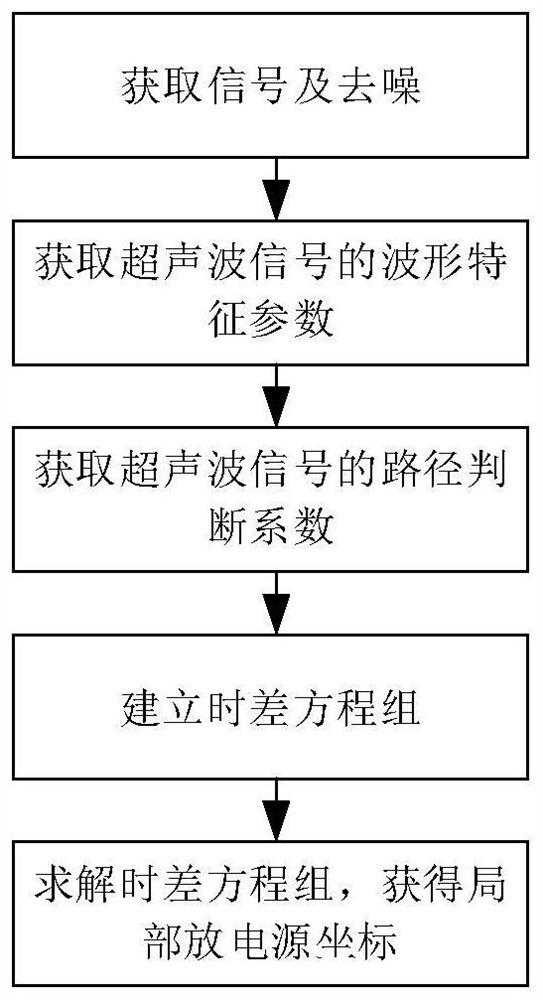
[0033]The implementation flow of the present invention will be further described below with reference to the accompanying drawings.

[0034]First step, get ultrasonic signals and denoising:

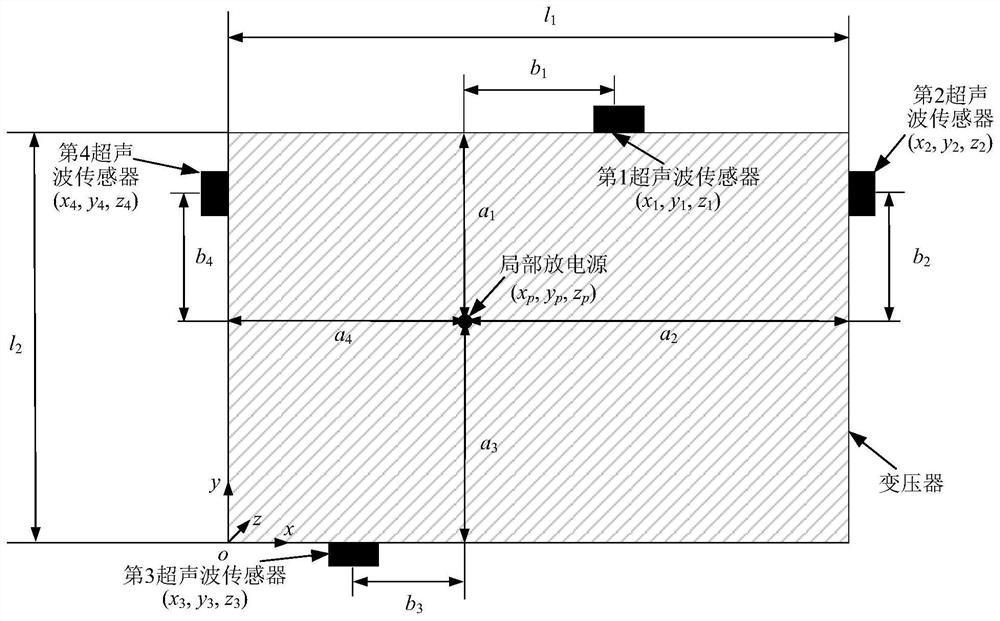
[0035]Gets the ultrasonic signal S received by four ultrasonic sensorsiWhere i = 1, 2, 3, 4 is the number of the ultrasonic sensor;1Ultrasonic signal received for the first ultrasonic sensor, S2Ultrasonic signal received for the second ultrasonic sensor, S3Ultrasonic signal received for third ultrasonic sensor, S4Ultrasonic signal received by the fourth ultrasonic sensor;

[0036]The coordinates of the first ultrasonic sensor (X1Y1,z1), The coordinate of the second ultrasonic sensor is (X2Y2,z2), The coordinates of the third ultrasonic sensor is (X3Y3,z3), The coordinates of the fourth ultrasonic sensor (X4Y4,z4), The coordinates of local power supply (XpYp,zp);

[0037]Ultrasound signal S with wavelet denoising methodiDenoising;

[0038]Ultrasonic signal S is acquired using a generalized cross-correlation me...


PUM


Abstract

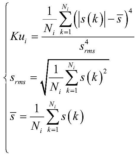
The invention discloses an ultrasonic positioning method for a partial discharge fault point of a traction transformer. Obtain ultrasonic signals and denoise through four ultrasonic sensors placed on the surface of the transformer; then analyze the collected ultrasonic waveforms to obtain waveform characteristic parameters, including peak-rise time ratio, kurtosis, peak frequency and spectral centroid; then obtain ultrasonic signals The judgment coefficient of the path can identify the propagation path of the ultrasonic signal; finally, the coordinates of the partial discharge source are obtained by establishing and solving the time difference equation. This method effectively improves the positioning accuracy and efficiency of transformer partial discharge discharge.

Description

Technical field[0001]The present invention belongs to the introduction of the traction power supply equipment online monitoring technology, and specifically, the present invention relates to a method of traction transformer local discharge failure point ultrasound positioning.Background technique[0002]Traction transformers are critical equipment in the traction power supply system, and its safe operation is significant. A large amount of information indicates that the main reason for the failure of the traction transformer is the deterioration of its insulation performance. Local discharge is the main reason for the insulation of transformer and is also one of the main signs, which is important for online detection and precise positioning. The ultrasonic signal is generated when the transformer is partially discharged, so detection and positioning the transformer partial discharge by detecting the ultrasonic signal.[0003]Due to the complex structure of the traction transformer, it i...

Claims


Application Information

Patent Timeline
Patent Type & Authority Patents(China)
IPC IPC(8): G01R31/12G01S5/22
CPCG01R31/1209G01S5/22
Inventor 蔡君懿周利军黎枝鑫
Owner SOUTHWEST JIAOTONG UNIV
Learn More