Supercharge Your Innovation With Domain-Expert AI Agents!

Splicing display device and splicing method thereof

A display device and a splicing technology, which is applied in the direction of instruments, nonlinear optics, optics, etc., can solve the problem that the display screen has a good effect in the distance

Active Publication Date: 2020-07-28
TCL CHINA STAR OPTOELECTRONICS TECH CO LTD
View PDF9 Cites 0 Cited by
  • Summary
  • Abstract
  • Description
  • Claims
  • Application Information

AI Technical Summary

Problems solved by technology

However, the non-display BM area (Black Matrix, that is, the black matrix area, also known as the black border area) between the two backlight modules in the splicing screen machine is generally not optimized, resulting in the spliced ​​display screen being viewed from a distance. Works well, but a very wide non-display area is noticeable on closer inspection

Method used


Image

  • Splicing display device and splicing method thereof
  • Splicing display device and splicing method thereof
  • Splicing display device and splicing method thereof

Examples


Embodiment 1

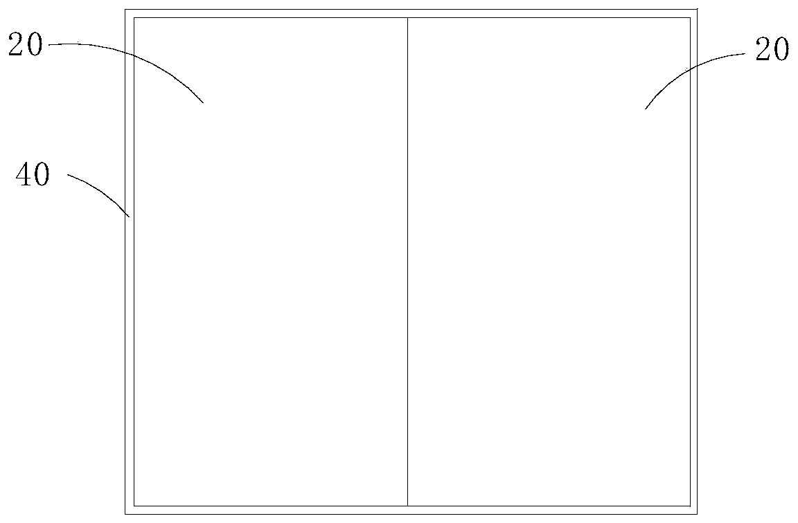
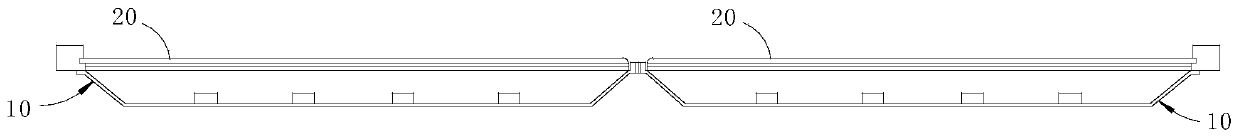
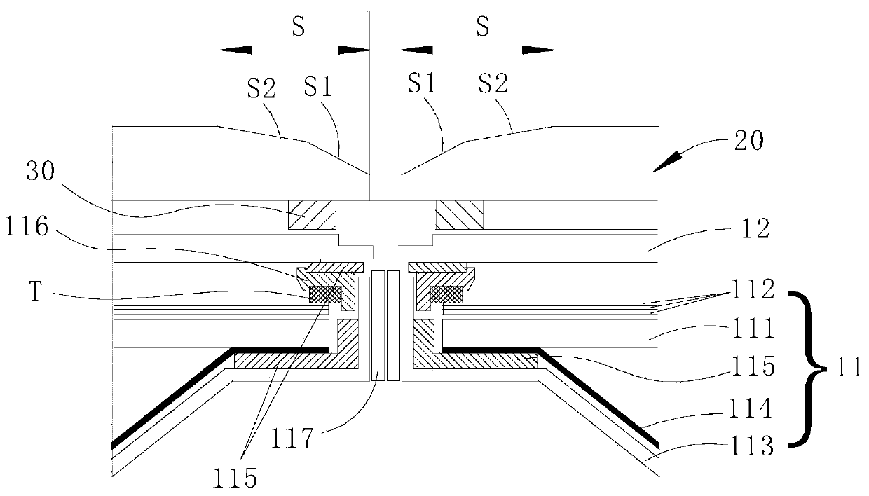
[0023] refer to Figure 1~3 , the spliced ​​display device of this embodiment includes a plurality of display devices 10 and a transparent optical layer 20, and all the display devices 10 are spliced ​​together adjacent to each other, and the light-emitting surface of each display device 10 is covered with a layer Optical layer 20. The display device 10 includes a central display area and a non-display area on the periphery of the display area. The periphery of the non-display area is a black matrix area (BM area), and the edges around the optical layer 20 are gradient areas S, which completely cover the black matrix. region, and the thickness of the gradient region S becomes thicker from the end of the optical layer 20 toward the center. Specifically, the bottom surface of the optical layer 20 is parallel to the upper surface of the display device 10 , and the thickness of the outermost periphery of the gradient region S of the optical layer 20 is the thinnest.

[0024] The...

Embodiment 2

[0031] like Figure 4 As shown, the difference from Embodiment 1 is that the buffer material 30 of this embodiment is made of light-shielding material, and the buffer material 30 on each display device 10 forms a closed ring, and the buffer material 30 is arranged directly above the black matrix area . Moreover, there is a gap between the end surface of the display device 10 and the buffer material 30 on the upper surface, that is, the end portion of the optical layer 20 protrudes from the buffer material 30 , and two adjacent optical layers 20 are separated by a certain distance. An auxiliary light source 50 is arranged in the area surrounded by the black matrix area, the buffer material 30, and the gradient area S of two adjacent display devices 10. The auxiliary light source 50 is preferably arranged at intervals along the circumference of the display device 10. The auxiliary light source 50 The emitted light is refracted by the gradient area and then emitted, so that the ...


PUM


Abstract

The invention discloses a splicing display device and a splicing method thereof. The splicing display device comprises a plurality of display devices and transparent optical layers, the display devices are adjacently spliced in pairs, and each optical layer covers a light emergence face of one display device. Each display device comprises a black matrix area on the outer peripheral of a non-display area, each optical layer comprises a marginal gradient area which completely covers the corresponding black matrix area, and each gradient area is thickened gradually from the end of the corresponding optical layer to the center. By the corresponding transparent optical layers on the light emergence faces of the splicing display device, special treatment of emergent rays at spliced positions is realized through the special marginal gradient area of each transparent optical layer, and a visual effect of black matrix area narrowing at the spliced position of the integral display device can be achieved.

Description

technical field [0001] The invention relates to the technical field of display screen splicing, in particular to a splicing display device and a splicing method thereof. Background technique [0002] With the continuous integration and development of LCD splicing technology and control technology, in the field of high-end large-screen display system engineering, large-screen image display through multi-screen splicing has been widely used. Screen display and clear and realistic display effects have greatly improved the work efficiency in monitoring, security, conferences, simulation and other fields, and at the same time promoted the rapid progress of the technical level of these industries. [0003] However, currently in the splicing screen market for commercial displays, the complete product of the flat splicing screen generally includes at least two display backlight modules, as well as the front frame and the back panel of the entire splicing screen. However, the non-di...

Claims


Application Information

Patent Timeline
Patent Type & Authority Patents(China)
IPC IPC(8): G02F1/1333G02F1/1335
CPCG02F1/13336G02F1/13338G02F1/1335
Inventor 陈伟丰唐国富陈锦雄
Owner TCL CHINA STAR OPTOELECTRONICS TECH CO LTD
Features
  • R&D
  • Intellectual Property
  • Life Sciences
  • Materials
  • Tech Scout
  • Unparalleled Data Quality
  • Higher Quality Content
  • 60% Fewer Hallucinations
Learn More