Brake caliper

A reset device and brake caliper technology, applied in the field of brake caliper, can solve problems such as noise, suspected brake system failure, poor vehicle quality, etc., and achieve the effect of avoiding random collisions

Inactive Publication Date: 2017-12-12
FORD GLOBAL TECH LLC
View PDF2 Cites 0 Cited by
  • Summary
  • Abstract
  • Description
  • Claims
  • Application Information

AI Technical Summary

Problems solved by technology

However, it may also occur that noise is emitted due to any impact of the brake disc against the brake pad, thus possibly leading the occupants of the vehicle to suspect a fault in the braking system
Screaming noises may also be present, which may lead passengers to conclude that the vehicle is of poor quality

Method used


Image

  • Brake caliper
  • Brake caliper
  • Brake caliper

Examples


Embodiment Construction

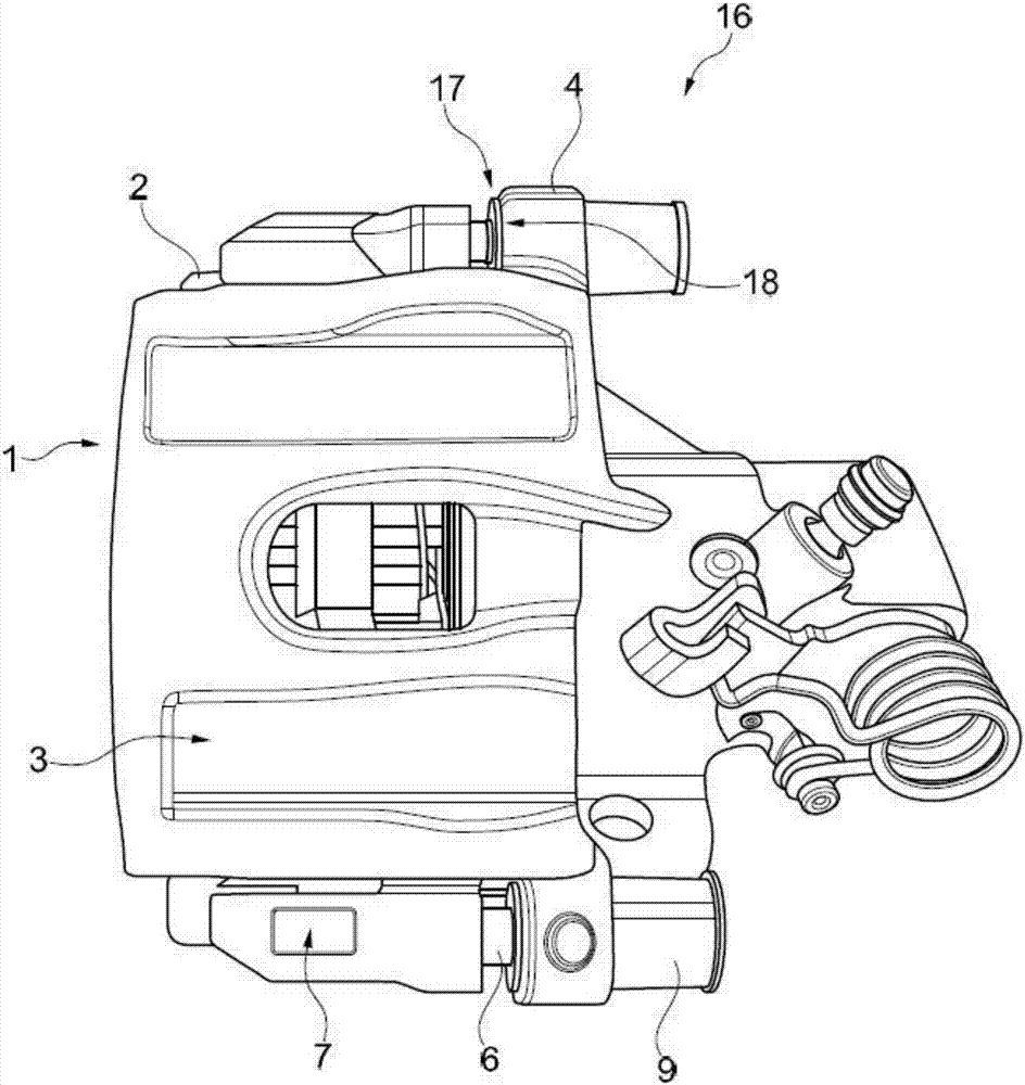
[0035] figure 1 The brake caliper is shown as floating caliper 1 in the exemplary embodiment. The floating forceps 1 has an anchor portion 2 , a fist forceps body 3 and a linear guide 4 . Brake pads (not shown) are held on the floating caliper. The inner brake pad is provided on one side of the floating caliper, which is the right side in the plane of the figure. Brake pistons (not shown) act directly on the inner brake pads. The other brake pad, ie the outer brake pad, is arranged in such a way as to be movably guided on the anchor 2 .

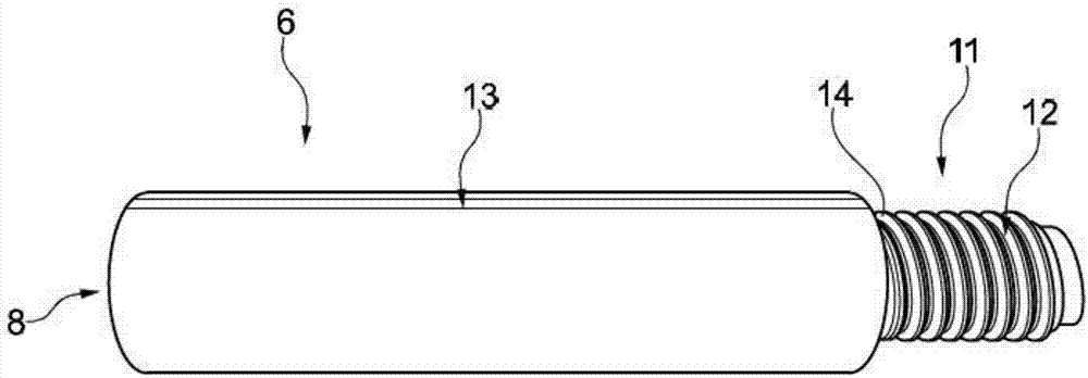
[0036] The linear guide 4 has guide elements 6 , which on the one hand are fastened in receptacles 7 of the anchor 2 . On the other hand, the guide element 6 passes through its free end 8 ( figure 2 ) is accommodated in the guide sleeve 9 of the fist-type forceps body 3 in a linearly movable manner. like figure 1 As can be seen, the floating pliers 1 has two guide elements 6, each of which is arranged laterally with respect to the anc...


PUM


Abstract

A brake caliper, for example a floating caliper, with a caliper housing and a guide element. The guide element fixed on one side to the caliper housing and moveably supported at a free end in a guide bushing. The guide bushing having a return mechanism that deflects with and returns the guide element to an initial position. The return mechanism also automatically adjusts when the guide element exceeds a predetermined amount of deflection.

Description

technical field [0001] The invention relates to a brake caliper according to the preamble of claim 1 , which brake caliper has an anchor and a fist caliper body and at least one linear guide rail with at least one guide element, which guides The element is fixed on one side and movably supported in the guide sleeve at its free end. Background technique [0002] For example, calipers like floating calipers are used in vehicle brakes. In the case of a floating caliper or sliding caliper, the brake piston is arranged behind only one of the brake pads, which are arranged on both sides of the brake disc, and the brake is further away from the brake piston The pads are attached to the floating clamp. In the case of wheel brakes, the brake piston is usually located on the side of the floating caliper opposite the wheel due to the limited installation space available, and therefore usually acts on the inner brake pad. The floating caliper is mounted so as to be able to move in th...

Claims


Application Information

Patent Timeline
Patent Type & Authority Applications(China)
IPC IPC(8): F16D65/02F16D65/097F16D65/52
CPCF16D65/02F16D65/097F16D65/52F16D55/226F16D55/22655F16D65/0068F16D65/0087F16D65/183F16D2200/0056
Inventor 菲利普·迈泽德克·谢弗
Owner FORD GLOBAL TECH LLC
Why Eureka
Try Eureka