Frequency-conversion direct-current aerator

A technology of frequency conversion DC and aeration machine, which is applied in the direction of AC motor control, electromechanical devices, and control of mechanical energy. It can solve the problems of easy degumming of magnetic steel sheets, limited rotating space of impellers, and small lifting force, so as to achieve enhanced reliability and Firmness, reduce the risk of burnout, easy installation and firm effect

Inactive Publication Date: 2017-12-15
张国余
View PDF6 Cites 3 Cited by
  • Summary
  • Abstract
  • Description
  • Claims
  • Application Information

AI Technical Summary

Problems solved by technology

The rotor with this structure has the following problems in the manufacturing process: when applying glue to each dovetail groove between the two dovetail groove projections, because of the dovetail groove of the dovetail groove projection, the glue is directly from the outer surface. It is inconvenient to smear, and glue smear is also easy to smear unevenly. When installing, push the magnetic steel sheet 13 from one side of the outer surface 111 of the fitting cylinder, and gradually push the inner surface 131 of the magnetic steel sheet 13 to completely fit the cylinder. The outer surface 111 of the cylinder. During the pushing process, the glue applied on the outer surface of the cylinder is pushed out, so that the glue on the inner surface of the magnetic steel sheet and the outer surface 111 of the cylinder is missing and the glue is uneven, which may cause the process. Repeated glue application affects the firmness between the magnetic steel sheet and the cylinder, reducing the service life of the entire rotor
In addition, this kind of rotor is easy to wear out the magnetic steel sheet during use, and the magnetic steel sheet on the rotor cylinder is easy to degumming, falling off or even cracking
[0005] In traditional aerators, there are two common structures for the impeller setting. One impeller type uses a metal impeller. The impeller is set at the center of the aerator under the motor. This structure has limited impeller rotation space, and the amount of oxygen that can be increased is limited by the power of the motor. 1. The size of the impeller has a great influence, the contact area between the impeller and the air is limited, the amount of oxygen added to the water body in a unit time is limited, and the noise is relatively large during operation; the other is the waterwheel type, and the impeller speed of this structure is not high , the lifting force on the bottom layer is not large, so it will not "arch the bottom of the pool", the weight of the whole machine is also light, it has a strong push flow ability and a certain mixing ability, and can obtain a better oxygen-liquid contact area and increase oxygen. The efficiency is high, but the impeller used in the traditional waterwheel type has the following defects: 1. The entire impeller is integrally formed of plastic material, and the entire impeller needs to be replaced if it is partially damaged; 2. Another impeller is a polygonal runner and the corresponding runner The variable number of blades are connected by plugging. Each side of the runner is provided with a protruding strip with the same length as the side, and the blade is provided with a slot with the same length as the side. When this structure is installed, due to the slot, The protruding strip is as long as the side, and requires a lot of force to achieve full engagement, and when installing the blade on one side, it is easy to touch the two adjacent blades on the side, so the installation space is limited, and the installation of the blade and the runner is very difficult. Inconvenient; 3. Most of the blade structures are through-holes in the middle, the impeller rotates, and the water flows directly through the holes. The water body of this structure passes through the through-holes in a large amount, and the resistance to the blades is also relatively large. The contact with the air The area is small, and the oxygen in the air cannot be effectively exchanged with the water body.

Method used


Image

  • Frequency-conversion direct-current aerator
  • Frequency-conversion direct-current aerator
  • Frequency-conversion direct-current aerator

Examples


Embodiment 1

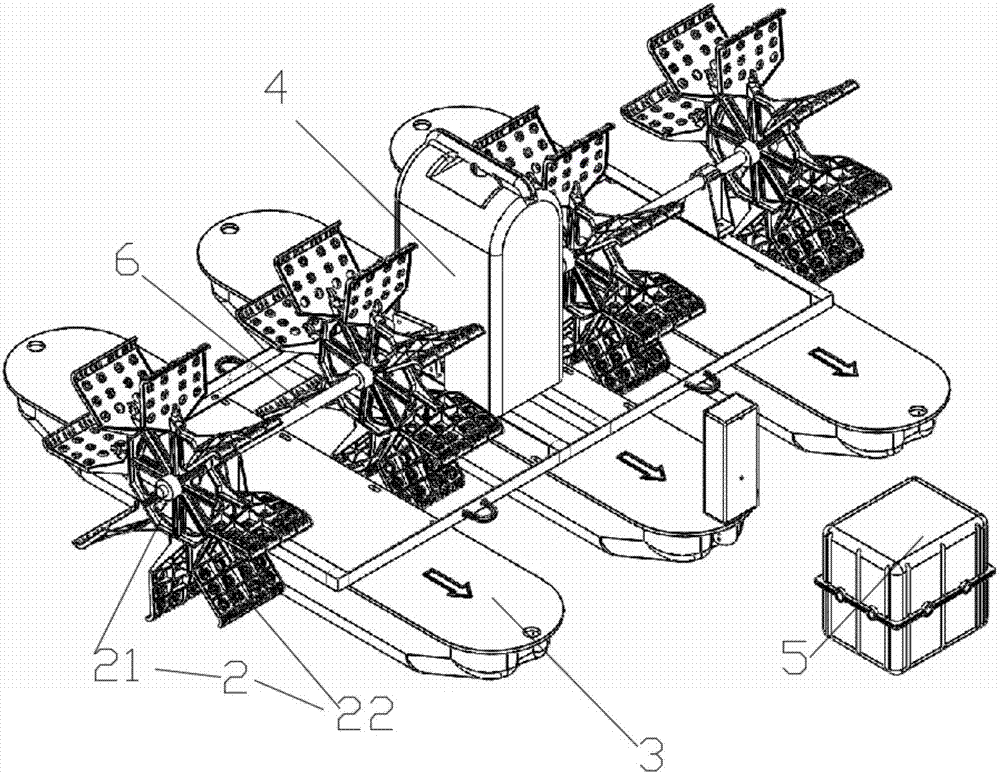
[0080] Such as figure 1 As shown, this embodiment discloses a frequency conversion DC aerator, including a floating body 3, a frequency conversion controller 5, a motor and an impeller 2, the motor is arranged on the floating body 3, the frequency conversion controller 5 is connected to the motor, and the The electric motor is connected with the impeller 2, and the frequency conversion controller converts the alternating current into direct current and outputs it to the electric motor. The present invention utilizes the frequency conversion controller to realize the frequency conversion to provide working direct current for the motor, uses the frequency conversion controller to slowly start the motor, reduces the impact on the water body, and prolongs the service life of the motor; The cost of replacement and maintenance in the water.

[0081] Place the floating body on the water, connect the frequency converter or other frequency conversion equipment with the motor and the ...

Embodiment 2

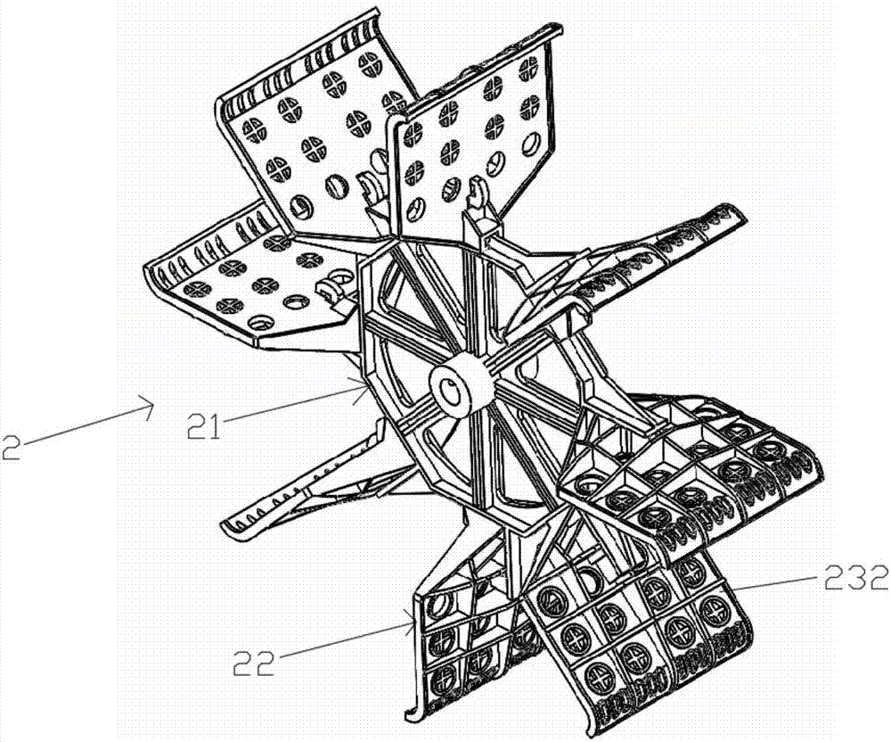
[0089] Different from Embodiment 1, the impeller 2 on the aerator of the present embodiment includes blade frame 21 and blade 22, blade frame 21 and blade 22 are detachably connected, blade frame 21 is a regular polygonal structure, any polygonal The side 211 of the structure is provided with a convex strip 212 which is smaller than the side length, the blade is provided with a card slot 221 matching with the convex strip, and the blade is provided with several rows of parallel water holes 222 .

[0090] The polygonal structure of the blade frame is a regular polygon, such as a hexagon or an octagon. The use of regular polygons is conducive to the balance of force during installation and use.

[0091] A sleeve 213 is arranged at the center of the polygonal structure of the blade frame, and the sleeve 213 is connected to the inner side 2111 of any side 211 of the polygonal structure through a connecting strip 214 . The gaps between the connecting bars can be used for water flo...

Embodiment 3

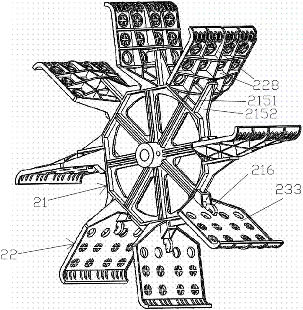
[0094] Different from Embodiment 2, the detachable connection between the blade frame 21 and the blade 22 in this embodiment is not limited to the mating connection between the convex strip and the slot, but also includes a further connection, the connection between the plug 216 and the socket 223 . Specifically, on any side 211 of the polygonal structure, a protruding portion 215 protruding outward is provided, and an inserting block 216 parallel to the protruding strip 212 is provided on the protruding portion 215, and an inserting block 216 corresponding to the inserting block 216 is provided on the blade 22. Socket 223, the installation connection of the blade and the blade frame is realized through the plug-in block and the socket. One end of the protrusion 212 is in contact with the protrusion 215 .

[0095] The insert block is provided with a "convex"-shaped side facing the protruding strip, that is, the inner surface 2162 of the insert block shown in the figure, and th...


PUM


Abstract

The invention discloses a frequency-conversion direct-current aerator. The aerator includes impellers, a floating body, a frequency conversion controller and a motor, wherein the motor is arranged on the floating body, the frequency conversion controller and the motor are sequentially connected, and the motor is connected to the impellers. The frequency-conversion direct-current aerator is characterized in that the frequency conversion controller converts an alternating current into a direct current and then outputs the direct current to the motor. The frequency-conversion direct-current aerator can directly use electric supply without constraint of three-phase electricity, and therefore the aerator has the advantages of being capable of saving more energy and electric power, less in energy consumption, endurable to high temperature, long in service life, convenient to install, and great in aeration and water stirring effects.

Description

technical field [0001] The invention belongs to the technical field of aquaculture, and in particular relates to a frequency conversion aeration machine using direct current. Background technique [0002] The aeration machine is a commonly used machine in the fishery and aquaculture industry. It drives the working parts through a power source such as an electric motor or a diesel engine, so that the "oxygen" in the air is quickly transferred to the equipment in the aquaculture water body. The machine is mainly used to increase The oxygen content in the water can ensure that the fish and other organisms in the water will not be hypoxic, and at the same time, it can also inhibit the growth of anaerobic bacteria in the water and prevent the deterioration of the pool water from threatening the living environment of the island fish. The machine generally uses its own air pump to drive air into the water, so as to achieve the purpose of increasing the oxygen content in the water. ...

Claims


Application Information

Patent Timeline
Patent Type & Authority Applications(China)
IPC IPC(8): A01K63/04H02K7/14H02P27/04H02K1/27H02K1/28H02J7/32
CPCA01K63/042H02J7/32H02K1/2706H02K1/28H02K7/14H02P27/04
Inventor 张国余张天健
Owner 张国余
Why Eureka
Try Eureka