Impeller-type aerator

An aerator and impeller-type technology, which is applied in the field of impeller-type aerators, can solve problems such as easy-to-wet control devices, limited impeller rotation space, and increased motor load power, so as to reduce the risk of burnout and avoid phase loss Problems, the effect of improving installation efficiency

Pending Publication Date: 2018-01-05
张国余
View PDF11 Cites 4 Cited by
  • Summary
  • Abstract
  • Description
  • Claims
  • Application Information

AI Technical Summary

Problems solved by technology

The rotor with this structure has the following problems in the manufacturing process: when applying glue to each dovetail groove between the two dovetail groove projections, because of the dovetail groove of the dovetail groove projection, the glue is directly from the outer surface. It is inconvenient to smear, and glue smear is also easy to smear unevenly. When installing, push the magnetic steel sheet 13 from one side of the outer surface 111 of the fitting cylinder, and gradually push the inner surface 131 of the magnetic steel sheet 13 to completely fit the cylinder. The outer surface 111 of the cylinder. During the pushing process, the glue applied on the outer surface of the cylinder is pushed out, so that the glue on the inner surface of the magnetic steel sheet and the outer surface 111 of the cylinder is missing and the glue is uneven, which may cause the process. Repeated glue application affects the firmness between the magnetic steel sheet and the cylinder, reducing the service life of the entire rotor
In addition, this kind of rotor is easy to wear out the magnetic steel sheet during use, and the magnetic steel sheet on the rotor cylinder is easy to degumming, falling off or even cracking
[0005] In traditional aerators, the impellers are mostly made of plastic. The surface of the plastic impeller is provided with a ring of water-feeding blades, and the height of the water-feeding blades is equal to the height of the plastic impeller. The impeller is set at the center of the aerator under the motor. This structure has limited rotation space for the impeller. , the amount of water fetched by the rotation of the water fetching blade is not large, and the amount of oxygen that can be increased is greatly affected by the power of the motor and the size of the impeller. The contact area between the impeller and the air is limited, and the amount of oxygen added to the water body in a unit time is limited, and there is noise during operation. Larger; the plastic impeller is easy to accumulate algae and moss during use, and it is easy to age when placed in water for a long time. The plastic blade needs a certain thickness, so it increases the resistance of rotation, affects the effect of oxygenation, and increases the load power of the motor. The whole three-phase motor has a high load and is easy to burn out; in addition, the impeller-type aerator is generally composed of an impeller, a motor, a control device, several floating bodies, etc., and an impeller is installed under the motor, and the impeller extends below the water surface. The control device realizes the control of the motor, and the rotation of the motor drives the impeller to rotate, and the rotation of the impeller drives the water to splash, so as to realize the purpose of oxygen in the air entering the water body; and in the aerator with this structure, the control device is set together with the motor and the impeller. During the process of impeller rotation and oxygenation, water splashes and easily wets the control device. Once the control device fails, it will cause problems such as electric leakage and aerator stop working. In serious cases, it may cause safety accidents

Method used


Image

  • Impeller-type aerator
  • Impeller-type aerator
  • Impeller-type aerator

Examples


Embodiment 1

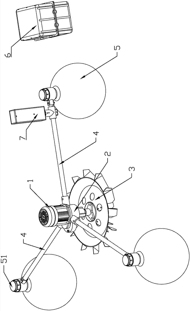
[0062] This embodiment relates to an impeller type aerator, such as Figure 1-8 As shown, it includes a frequency conversion controller, a motor 1, a reducer 2, and an impeller 3 connected in sequence. The reducer is connected to the floating body 5 of the whole machine through a strut 4. The frequency conversion controller converts alternating current into direct current and outputs it to the electric motor.

[0063] Place the floating body on the water, connect the frequency converter or other frequency conversion equipment with the motor and the controller, the controller sends the start action, and the frequency converter converts the single-phase AC power of the grid, such as 220V, into a DC power of the rated voltage of the motor, and outputs it to the motor, and the motor Drive the impeller to rotate, and the impeller is between the water body and the air, so that the whole aerator works to increase the oxygen of the water body.

[0064] In order to avoid water splashi...

Embodiment 2

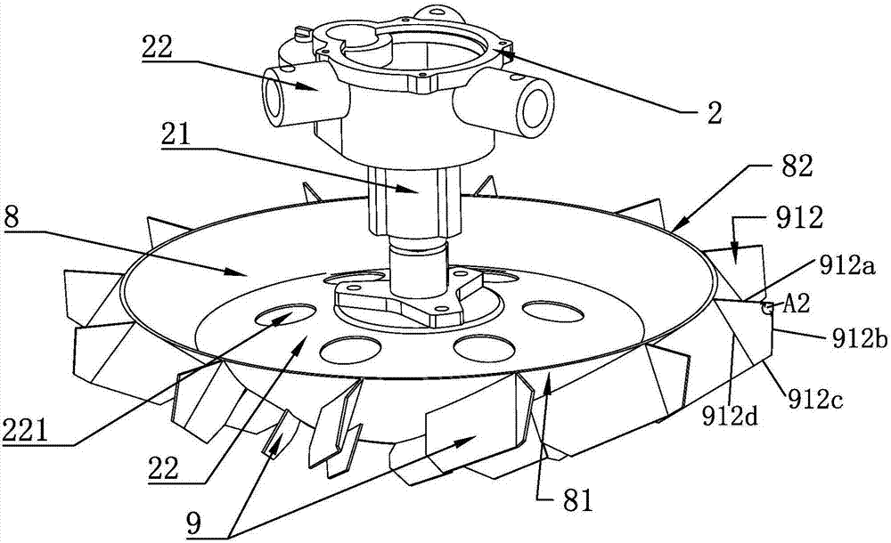
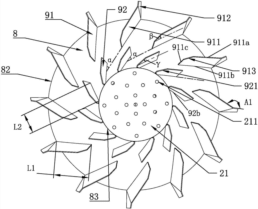
[0076] Different from Embodiment 1, the impeller 3 in this embodiment includes an impeller disc 8 and several blades 9, such as Figure 1-8 As shown, the plurality of blades are arranged on the surface of the impeller disk in two circles up and down in a radial shape. The directions of radial arrangement of the blades on the upper and lower circles are the same, image 3 Described in the radial arrangement in a clockwise direction.

[0077] The impeller disk 8 adopts a rounded platform structure formed by connecting fan ring plates end to end, and the blades 9 shown are arranged on the outer surface 81 of the impeller disk 8 .

[0078] The blade 9 includes an upper blade 91 and a lower blade 92 , the upper blade is arranged on the upper side of the impeller disk 8 , and the lower blade is arranged on the lower side of the impeller disk 8 . Wherein, the extension line of any one of the lower blades 92 is located between two adjacent upper blades 91, adopting this staggered ar...

Embodiment 3

[0084] Same as Embodiment 2, the included angle between the upper blade 91, the lower blade 92 and the impeller disc in this embodiment is 0-90 degrees. The optimal setting is that the angle between the upper blade and / or the lower blade and the outer surface of the impeller disk is 45 degrees or 60 degrees or is tangent. The area of ​​the upper blade is greater than that of the lower blade, preferably the upper blade is greater than or equal to 1.5 times the area of ​​the lower blade.

[0085] As a preferred setting, the angle of inclination of the upper blade or the lower blade is different.

[0086] As a preferred setting, the extension line of any one blade 9 does not intersect with the central axis of the impeller disk.

[0087] In this embodiment, the entire impeller is made of 304 stainless steel or other rust-proof and light-weight metals. The pH of the water body is unstable, and there are a lot of microorganisms in the water body. The use of 304 stainless steel avoid...


PUM


Abstract

The invention discloses an impeller-type aerator. The impeller-type aerator comprises a frequency conversion controller, a motor, a speed reducer, an impeller, supporting rods and whole-machine floating bodies, wherein the frequency conversion controller, the motor, the speed reducer and the impeller are sequentially connected, the speed reducer is connected with the whole-machine floating bodiesthrough the supporting rods, and the frequency conversion controller converts alternating currents into direct currents to output to the motor. The impeller-type aerator has the advantages that impeller-type aerator is not limited by three-phase electricity, energy and electricity are saved, the aeration effect is good, installation is convenient and rapid, and using is safer.

Description

technical field [0001] The invention belongs to the technical field of aquaculture, and in particular relates to an impeller type aerator. Background technique [0002] The aeration machine is a commonly used machine in the fishery and aquaculture industry. It drives the working parts through a power source such as an electric motor or a diesel engine, so that the "oxygen" in the air is quickly transferred to the equipment in the aquaculture water body. The machine is mainly used to increase The oxygen content in the water can ensure that the fish and other organisms in the water will not be hypoxic, and at the same time, it can also inhibit the growth of anaerobic bacteria in the water and prevent the deterioration of the pool water from threatening the living environment of the island fish. The machine generally uses its own air pump to drive air into the water, so as to achieve the purpose of increasing the oxygen content in the water. The use of an aerator can not only ...

Claims


Application Information

Patent Timeline
Patent Type & Authority Applications(China)
IPC IPC(8): A01K63/04
Inventor 张国余张天健
Owner 张国余
Why Eureka
Try Eureka