
Spiral shaver head

A razor and spiral technology, applied in the field of electric shaver heads, can solve the problems of not so clean shaving effect, pulling beards, etc., to achieve clean shaving effect, overcome vibration, and avoid pulling beards. Effect

Inactive Publication Date: 2017-12-15
ZHONGBEI UNIV
View PDF6 Cites 0 Cited by
  • Summary
  • Abstract
  • Description
  • Claims
  • Application Information

AI Technical Summary

Problems solved by technology

However, compared with reciprocating products, the shaving effect is not so clean. It needs to be repeated several times to remove the beards in the dead corners, and the shaving process needs to be artificially moved back and forth to increase the shaving effect, and there is a phenomenon of pulling beards

Method used


Image

  • Spiral shaver head
  • Spiral shaver head
  • Spiral shaver head

Examples


Embodiment 1

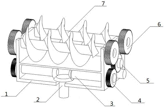
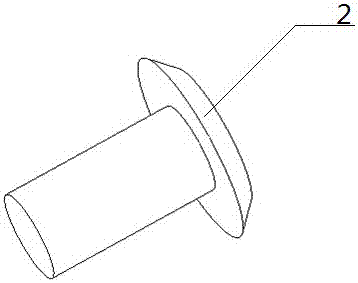
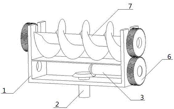
[0016] Such as figure 1 , figure 2 As shown, the present invention is a spiral shaver head. When the shaver is working, the rechargeable battery provides power to the input bevel gear shaft 2, and its high-speed rotation is output in two parts, and one part is transmitted to the driven bevel gear 4. The driven bevel gear 4 is transmitted through the driven bevel gear shaft and several cylindrical gears 6, and finally output by the helical cutter 8; in the transmission process, multiple cylindrical gears 6 can be designed, which has two purposes: the first purpose The purpose is to ensure that the two helical cutters 8 turn in opposite directions, and the second purpose is to obtain a suitable rotation speed, so engineers can increase or decrease the number of spur gears 6 as needed during specific implementation. In the current figure 1 Among them, there are three cylindrical gears 6 to transmit the power from the motor to the screw cutter 7. Of course, this process requires...

Embodiment 2

[0019] Such as Figure 4 As shown, it includes a driving bevel gear 3, a driven bevel gear 4, two cylindrical gears 6, a helical cutter 8, and a single helical support 9. This structure has the characteristics of lightness, flexibility, and long shaving time; When the shaver is working, the rechargeable battery provides power to the input bevel gear shaft 2, and its high-speed rotation is output in two parts, one part is transmitted to the driven bevel gear 4, and the driven bevel gear 4 passes through the driven bevel gear shaft and several cylindrical gears 6 transmission, finally output by the spiral knife 8;.

[0020] At present, these two schemes use the razor of the spiral razor head, and its thin mesh cover is fixed and connected with the bracket 1. Of course, an elastic connection shaft can also be designed between the cylindrical gear 6 and the helical cutter 8. In this way, the thin mesh cover can translate to the motor along the direction of the active bevel gear s...


PUM


Abstract

The invention provides a spiral shaver head which structurally comprises a bracket, an input bevel gear shaft, a driven bevel gear shaft, driven bevel gears, driving bevel gears and cylindrical gears. The bracket is divided into an upper layer structure and a lower layer structure; shaver mounting frames are arranged at the left end and the right end of the bracket; a mounting hole is formed in the middle of the lower layer bracket structure and used for mounting of the input bevel gear shaft; the driving bevel gears are arranged the top end of the input bevel gear shaft; the driven bevel gears and the driving bevel gears are engaged with each other; and the driven bevel gear shaft transversely extends out of mounting holes in the two sides of the bracket to drive the cylindrical gears to rotate. According to the spiral shaver head, the function of the reciprocating shaver is realized through a spiral blade structure; continuous unidirectional shaving is achieved through the circumferential movement of the spiral shaver, so that the shaving effect is cleaner; and through shaving of bidirectional spiral blades, the comfort, stability and cleanliness of the shaver are guaranteed, and the phenomenon that a rotary shaver drags beards is effectively avoided.

Description

technical field [0001] The invention relates to the field of electric shaver heads, in particular to a spiral electric shaver head. Background technique [0002] There are two types of electric shavers currently on the market: reciprocating and rotary. The high speed of the reciprocating shaver motor provides powerful power. The fast-rotating motor drives the blades that swing left and right to shave the beard cleanly and easily, and the blades that swing left and right will never be scratched by the rotary shaver. The phenomenon of beard pulling. The disadvantage of the reciprocating type is that the vibration of the shaver is obvious during use, and the noise is relatively large. This is related to the high-speed motor and the movement mode of the blade. It is not conducive to local shaving. Easy to shave. The rotary shaver rotates in the center, and the circular motion can continuously cut and shave the beard in one direction, which not only makes the shave more clean ...

Claims


Application Information

Patent Timeline
Patent Type & Authority Applications(China)
IPC IPC(8): B26B19/14
CPCB26B19/145
Inventor 毛虎平
Owner ZHONGBEI UNIV
Learn More