Pseudo-satellite layout method used for improving positioning precision

A layout method and positioning accuracy technology, applied in the field of pseudolite positioning, can solve problems such as inability to obtain positioning results, and achieve the effect of improving accuracy

Active Publication Date: 2017-12-19
UNIV OF ELECTRONICS SCI & TECH OF CHINA
View PDF3 Cites 7 Cited by
  • Summary
  • Abstract
  • Description
  • Claims
  • Application Information

AI Technical Summary

Problems solved by technology

However, for a particular user, such as a user at a fixed point, these layouts may not achieve optimal targeting results

Method used


Image

  • Pseudo-satellite layout method used for improving positioning precision
  • Pseudo-satellite layout method used for improving positioning precision
  • Pseudo-satellite layout method used for improving positioning precision

Examples


Embodiment Construction

[0018] Exemplary embodiments of the present invention will now be described in detail with reference to the accompanying drawings. It should be understood that the implementations shown and described in the drawings are only exemplary, intended to explain the principle and spirit of the present invention, rather than limit the scope of the present invention.

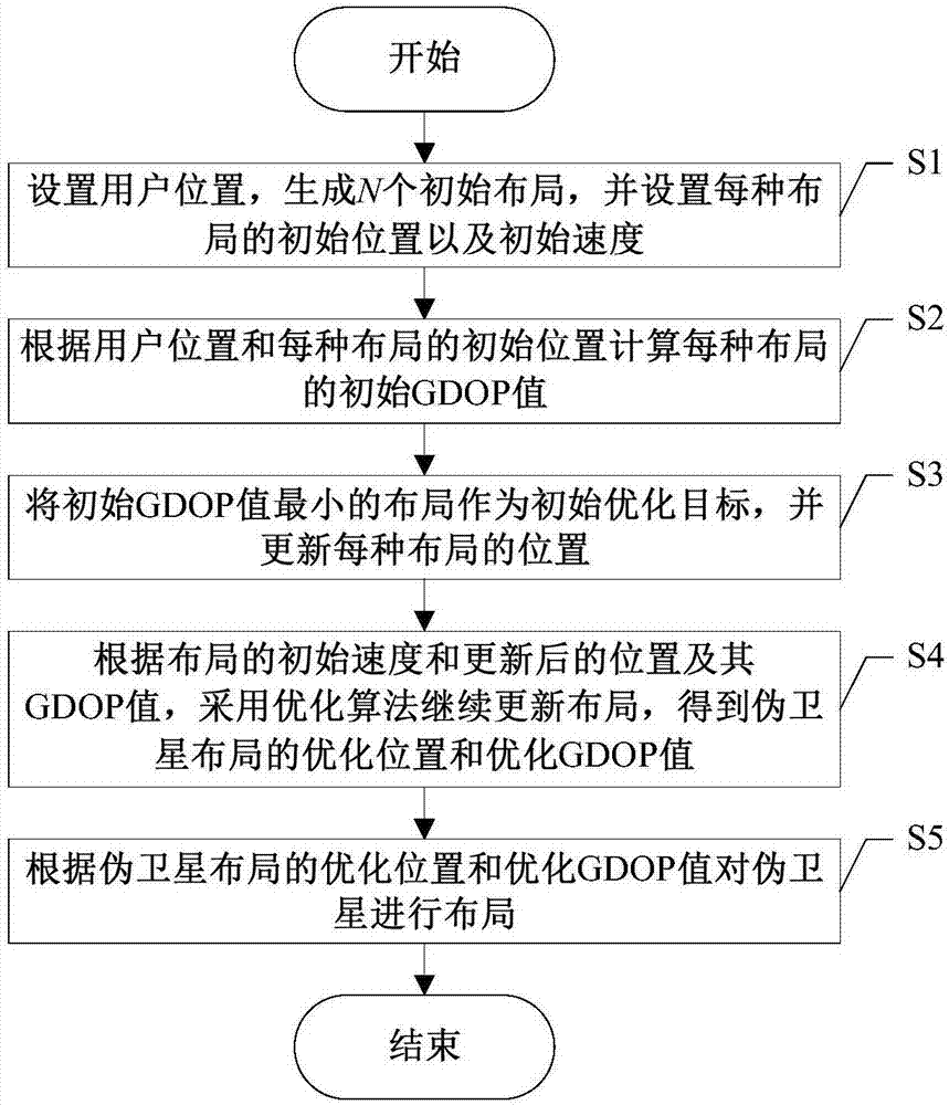
[0019] Embodiments of the present invention provide a pseudolite layout method for improving positioning accuracy, such as figure 1 As shown, including the following steps S1-S5:

[0020] S1. Set the user position, generate N initial layouts, and set the initial position and initial speed of each layout.

[0021] The three-dimensional positions of n pseudolites (x j ,y j ,z j ) are combined into a Q-dimensional layout, where j=1,2,...,n, Q=n×3. A total of N layouts are set, where the position of the i-th layout is denoted as S i =(s i1 ,s i2 ,...,s iQ ), the velocity is denoted as v i =(v i1 ,v i2 ,...,v iQ ...


PUM


Abstract

The invention discloses a pseudo-satellite layout method used for improving positioning precision. Based on effects on satellite layout statuses imposed by a GDOP value, the GDOP value corresponding to a classic layout is firstly calculated, then by use of an optimization algorithm, the GDOP value is optimized, and the optimized pseudo-satellite layout is applied to the positioning so that a high-precision user positioning result is obtained. According to the invention, the positioning efficiency is effectively improved and the method can be expanded to layout of pseudo-satellite of any number.

Description

technical field [0001] The invention belongs to the technical field of pseudolite positioning, and in particular relates to the design of a pseudolite layout method for improving positioning accuracy. Background technique [0002] At present, the global satellite navigation system has been widely used in the fields of navigation, positioning and measurement, but the navigation satellites are distributed at a height of 20,000 km above the ground, which makes the user's vertical positioning accuracy poor, and the number of visible satellites is affected by the weather and other natural environments. Therefore, it is necessary to introduce pseudolites to solve these two problems. The introduction of pseudolites can improve the layout of the satellite system, thereby significantly improving the positioning accuracy, so many researchers have conducted a lot of research on this. [0003] Young et al. used the positioning matrix to conclude that increasing the number of pseudolite...

Claims


Application Information

Patent Timeline
Patent Type & Authority Applications(China)
IPC IPC(8): G01S19/11
CPCG01S19/11
Inventor 宋劼李洪星王坚李桓李玉柏
Owner UNIV OF ELECTRONICS SCI & TECH OF CHINA
Why Eureka
Try Eureka