
A nail transporting device and a screwing manipulator system with the device

A technology of nail transport and motion mechanism, which is applied in the field of machinery, can solve the problems of difficult application of air-blown nail transport equipment, complex technical structure, stacked nails, and nail clamping, etc., and achieves high reliability, simple and compact structure, and stable performance. Effect

Active Publication Date: 2019-04-30
天津新松机器人自动化有限公司
View PDF7 Cites 0 Cited by
  • Summary
  • Abstract
  • Description
  • Claims
  • Application Information

AI Technical Summary

Problems solved by technology

[0003] At present, most of the screws used in the home appliance industry and the 3C industry are flat screws, and it is difficult to apply common air blowing nail transport equipment, so it is urgent to design a nail transport mechanism suitable for flat screws, which can be applied to robots. Screwing screws instead of humans
[0004] Chinese patent (CN104723054A) discloses a device for transporting screws. Because of its complex technical structure, the screws slide down due to gravity, which is prone to stacked nails and stuck nails, and has poor stability.

Method used


Image

  • A nail transporting device and a screwing manipulator system with the device
  • A nail transporting device and a screwing manipulator system with the device
  • A nail transporting device and a screwing manipulator system with the device

Examples


Embodiment Construction

[0028] In order to enable those skilled in the art to better understand the solutions of the present invention, the following will clearly and completely describe the technical solutions in the embodiments of the present invention in conjunction with the drawings in the embodiments of the present invention. Obviously, the described embodiments are only It is an embodiment of a part of the present invention, but not all embodiments. Based on the embodiments of the present invention, all other embodiments obtained by persons of ordinary skill in the art without making creative efforts shall fall within the protection scope of the present invention.

[0029] The terms "first", "second", "third", "fourth", etc. (if any) in the description and claims of the present invention and the above drawings are used to distinguish similar objects and not necessarily Describe a specific order or sequence. It is to be understood that the terms so used are interchangeable under appropriate cir...


PUM


Abstract

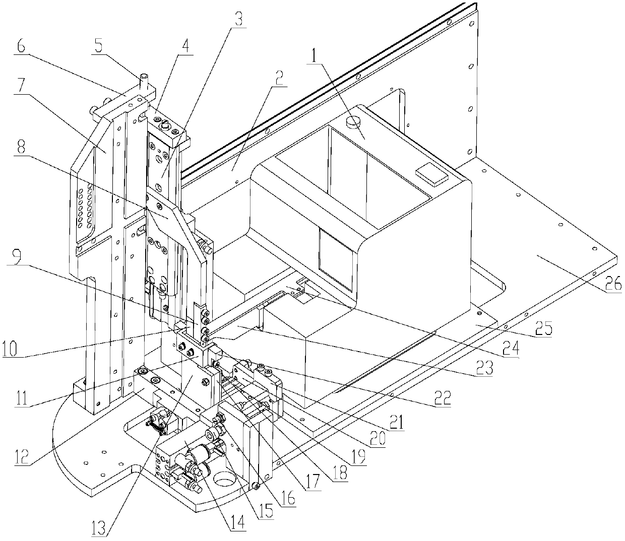
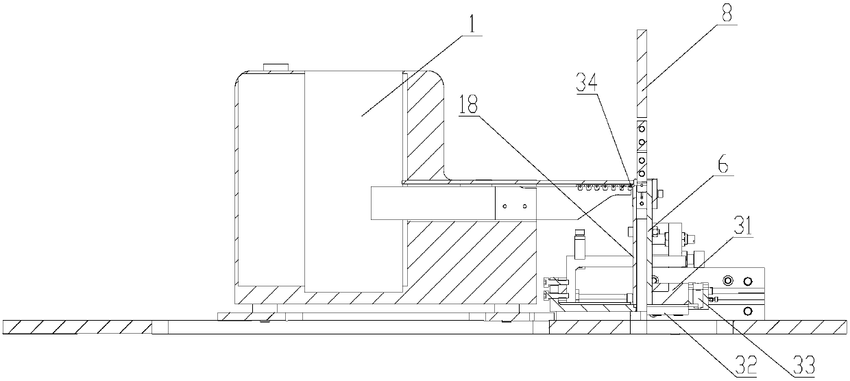
The embodiment of the invention provides a screw conveying device. The screw conveying device comprises a screw supplying structure, a first movement mechanism used for conveying screws provided by the screw supplying structure to the first position, a second movement mechanism used for conveying the screws conveyed to the first position to the second position, a screwdriver nozzle arranged at thesecond position and an installation frame used for bearing all the above parts. By the adoption of the screw conveying device, the manner that a pneumatic element is used for conveying the screws isadopted, one screw is conveyed each time, the phenomena of screw stacking and screw clamping are not likely to happen, the structure is simple and compact, the performance is stable, reliability is high, and due to the fact that the extruding frictional wear among the screws is reduced, the beneficial effects of energy conservation and environment friendliness can also be achieved.

Description

technical field [0001] The invention relates to the field of machinery, in particular to a nail driving device and a screwing manipulator system with the device. Background technique [0002] The automatic screwdriver is mainly composed of sorting, separating and locking. Compared with the screw locking method of holding the screw in one hand and the electric screwdriver in the other hand, the automatic screw locking machine can free one hand, and only need to align the screw hole with one hand to lock the screw. After locking a screw, you only need to lift the screwdriver to align with the next screw hole to lock the screw. The machine will automatically transport a screw to the mouthpiece at the moment of lifting the screwdriver, waiting for the next screw to be locked, and so on. [0003] At present, most of the screws used in the home appliance industry and the 3C industry are flat screws, and it is difficult to apply common air blowing nail transport equipment, so it i...

Claims


Application Information

Patent Timeline
Patent Type & Authority Patents(China)
IPC IPC(8): B23P19/00B23P19/06
Inventor 王金涛夏常玖曲道奎朱维金徐方郭海冰王芮琳
Owner 天津新松机器人自动化有限公司
Learn More