Damping of sensor

A sensor, sensor signal technology, used in instruments, measuring instrument components, gyroscopes/steering sensing devices, etc., to solve problems such as increasing space requirements

Inactive Publication Date: 2018-01-09
INFINEON TECH AG
View PDF9 Cites 7 Cited by
  • Summary
  • Abstract
  • Description
  • Claims
  • Application Information

AI Technical Summary

Problems solved by technology

However, such schemes also face certain disadvantages and constraints
The MEMS pressure sensor and the second sensor are integrated separately, which still results in increased space requirements on the substrate

Method used


Image

  • Damping of sensor
  • Damping of sensor
  • Damping of sensor

Examples


example 1

[0073] Example 1. A device comprising:
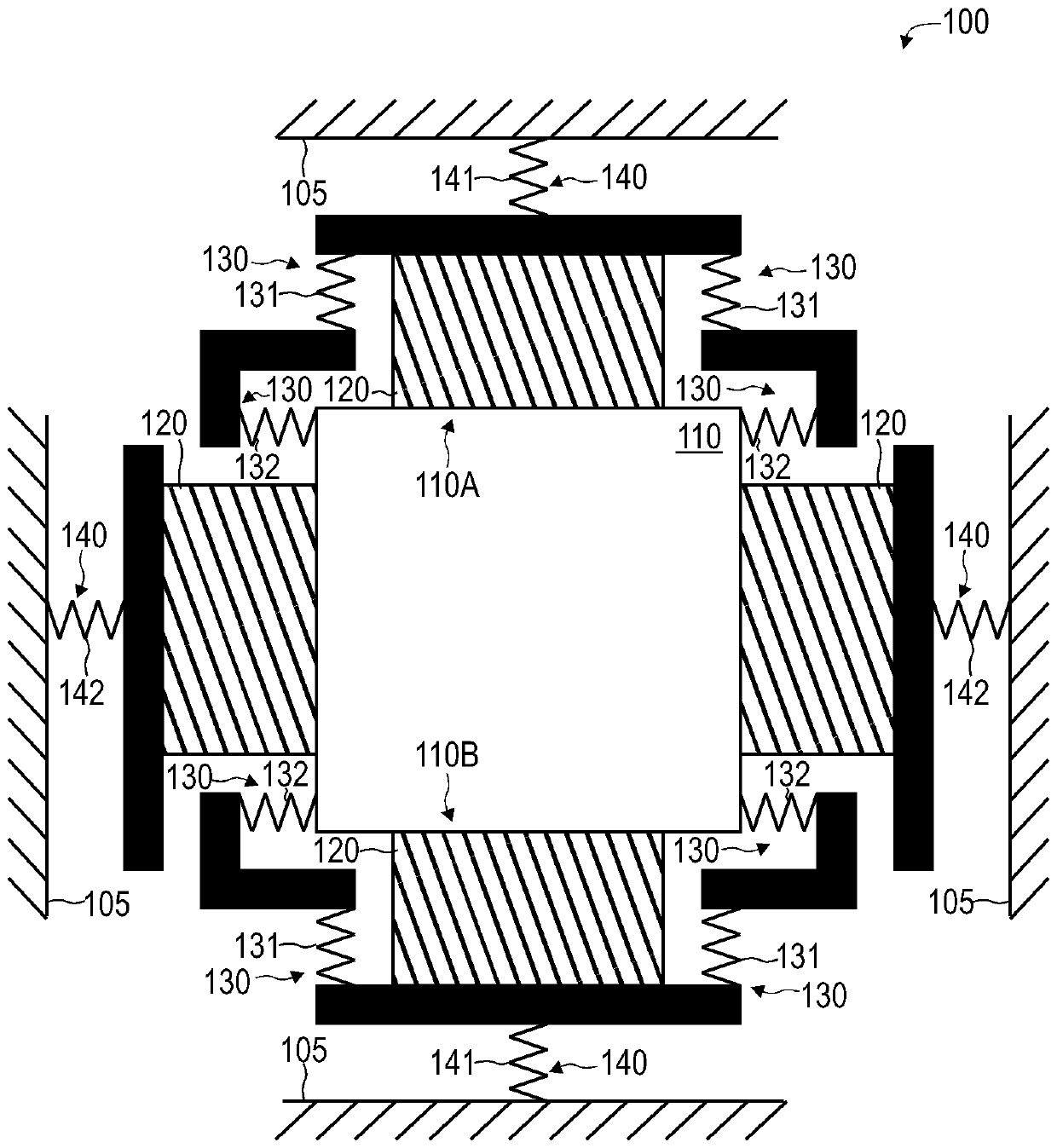
[0074] - substrate,

[0075] - spring structure,

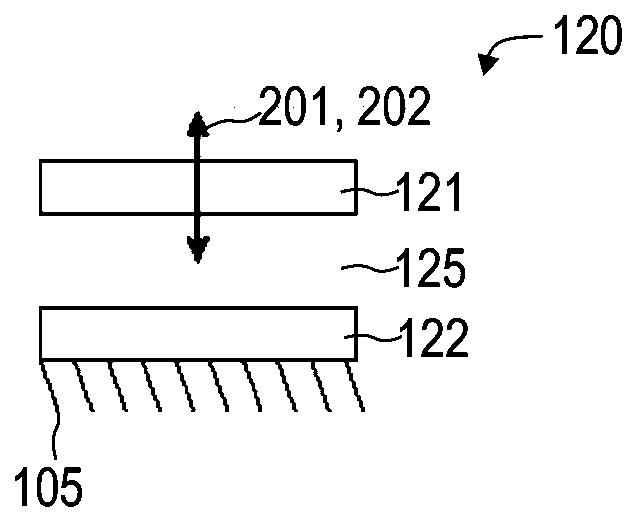
[0076] - a first sensor resiliently coupled to the substrate via a spring structure configured to provide vibration damping of the first sensor with respect to the substrate, and

[0077] - A second sensor configured to sense the deflection of the spring structure.

example 2

[0078] Example 2. The device of Example 1,

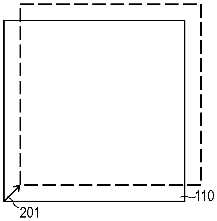
[0079] Wherein the spring structure is configured to provide at least two degrees of freedom of movement to the first sensor.

example 3

[0080] Example 3. The device of Example 2,

[0081] wherein the spring structure comprises at least one first micromechanical element providing a first degree of freedom of translational motion to the first sensor, and further comprises at least one second micromechanical element providing a second degree of freedom of translational motion to the first sensor, so The second degree of freedom is different from the first degree of freedom.


PUM


Abstract

The invention relates to damping of a sensor. A device comprises a substrate, a spring structure, and a first sensor. The first sensor is resiliently coupled with the substrate via the spring structure. The spring structure is configured to provide damping of the first sensor with respect to the substrate. The device also comprises a second sensor configured to sense a deflection of the spring structure.

Description

technical field [0001] Various examples relate to a device that includes a substrate, a spring structure, and a first sensor. The first sensor is resiliently coupled to the substrate via a spring structure. The spring structure is configured to provide damping of the first sensor with respect to the substrate. The device also includes a second sensor configured to sense a deflection of the spring structure. Background technique [0002] Microelectromechanical systems (MEMS) are desirable for sensing, for example, environmental pressure due to their compact integration capabilities and availability of flexible design options. The potential applications are enormous: navigation or positioning applications could benefit from correlating changes in environmental pressure with changes detected in the elevation of the corresponding device. [0003] However, it is known that changes in the sensor signal of MEMS pressure sensors may be caused by further external influences than c...

Claims


Application Information

Patent Timeline
Patent Type & Authority Applications(China)
IPC IPC(8): G01D11/10G01L9/00G01P15/00
CPCB81B7/0016G01C19/5783B81B2201/0235B81B2201/0264G01L19/146G01D11/10G01P15/125G01P2015/0882G01D11/18B81B3/0018B81B7/02G01C19/5726G01P1/003H05K5/03
Inventor M.豪博尔德
Owner INFINEON TECH AG
Why Eureka
Try Eureka