

Underbody structure of automobile
A car body and automobile technology, applied in the direction of substructure, superstructure, vehicle parts, etc.
- Summary
- Abstract
- Description
- Claims
- Application Information
AI Technical Summary
Problems solved by technology
Method used
Image

Examples
Embodiment Construction
[0032] An embodiment of the present invention will be described in detail below based on the drawings.
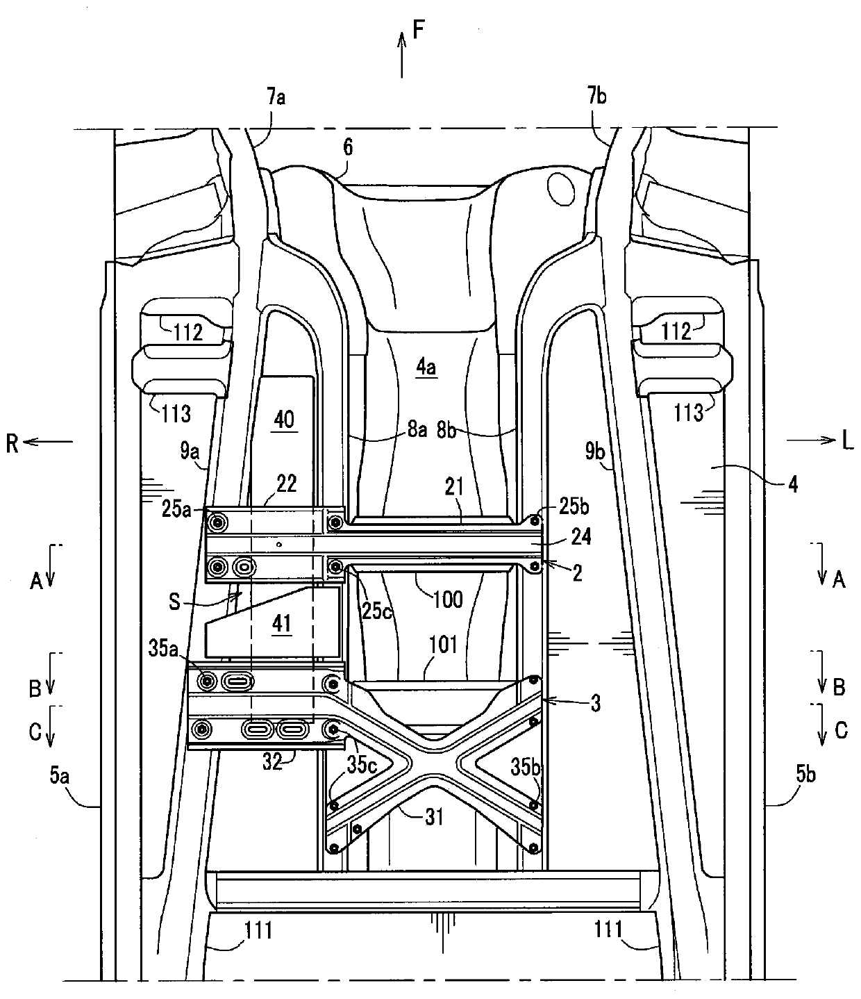
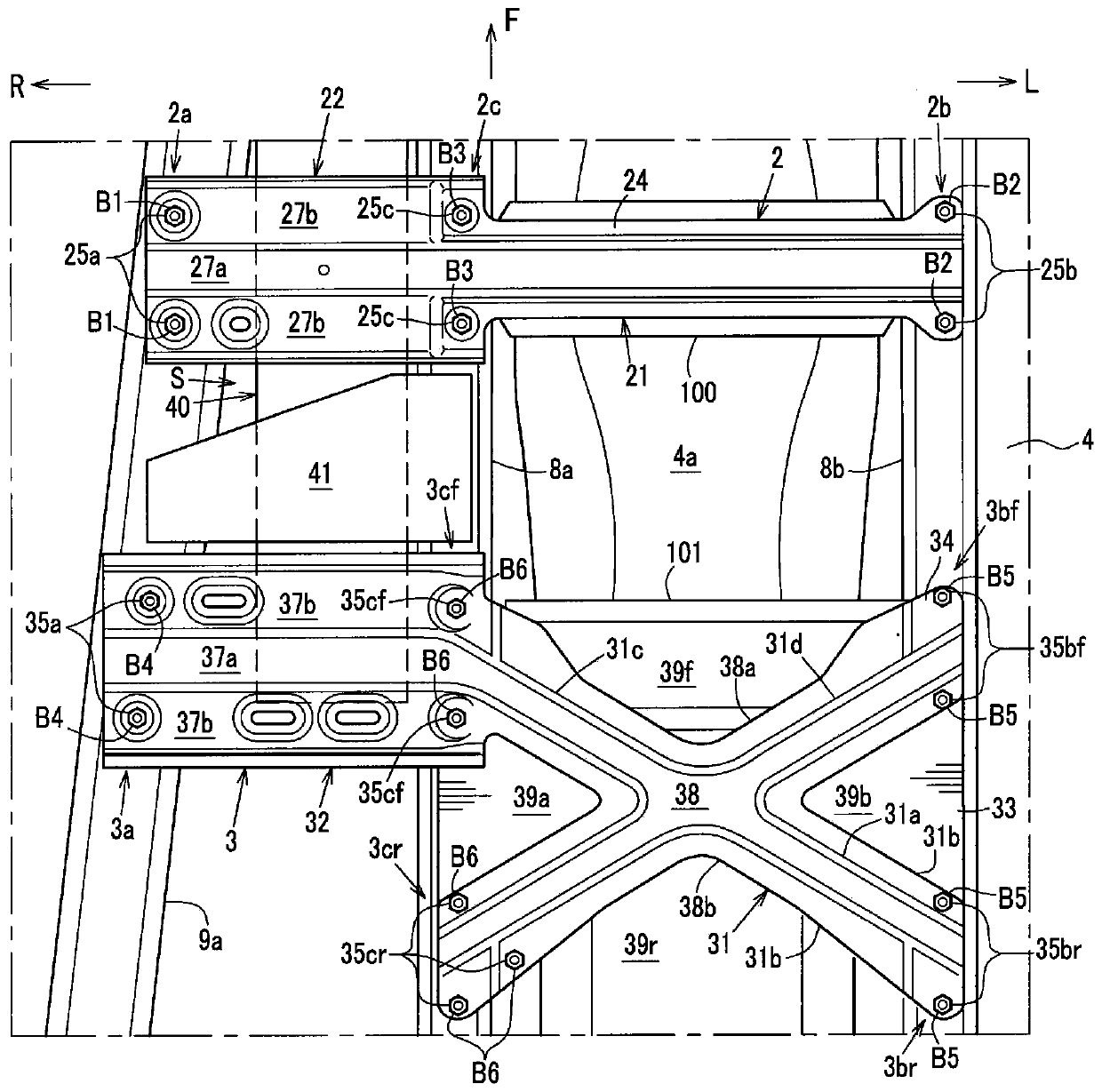
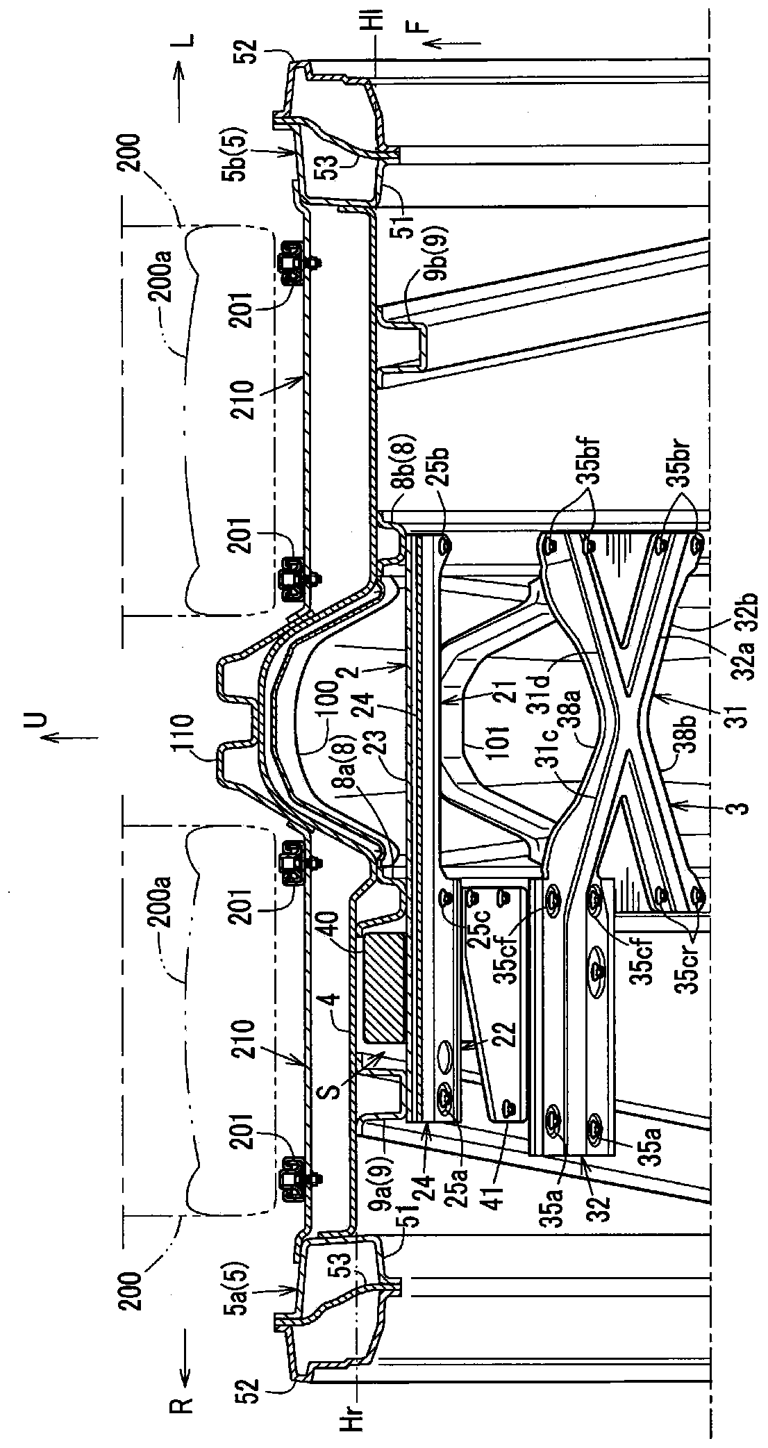
[0033] figure 1 is a bottom view of the lower body structure of the automobile of this embodiment, figure 2 yes figure 1 The main part of the enlarged figure, image 3 viewed from above figure 1 A three-dimensional cross-sectional view of the main part of the A-A line, Figure 4 It is a longitudinal sectional view showing the main part of the central part in the width direction of the channel part, Figure 5 (a) is viewed from obliquely above figure 1 The three-dimensional cross-sectional view of the main part of the B-B line in, Figure 5 (b) is figure 1 A cross-sectional view of the main part of the C-C line, Image 6 (a) is a perspective view of the upper side panel of the front side underfloor beam viewed obliquely from above in front, Image 6 (b) is with Image 6 An enlarged sectional view of the beam under the front floor corresponding to line D-D in (a), ...
PUM
 Abstract
Description
Claims
Application Information