Construction method of an integral layered filling device

A filling device and construction method technology, applied in the direction of mining fluid, earthwork drilling, wellbore/well components, etc., can solve the problems that single-layer filling tools cannot be filled in layers and are difficult to move, so as to avoid sand settlement and overcome connection problems. Difficulty, the effect of improving work efficiency

Inactive Publication Date: 2019-12-06
SUZHOU YUANLIAN SCI & TECH PIONEER PARK MANAGEMENT CO LTD
View PDF8 Cites 0 Cited by
  • Summary
  • Abstract
  • Description
  • Claims
  • Application Information

AI Technical Summary

Problems solved by technology

[0005] The purpose of the present invention is to address the above-mentioned defects in the prior art, to provide a construction method of an integral layered filling device, which solves the problem that a single-layer filling tool cannot be filled in layers, and also overcomes the problem of the existing design of the inner filling pipe. There is a problem that the column and the outer packing string are difficult to move, and at the same time, the ground filling and ring filling of the oil layer are realized, which improves the efficiency

Method used


Image

  • Construction method of an integral layered filling device
  • Construction method of an integral layered filling device
  • Construction method of an integral layered filling device

Examples


Embodiment 1

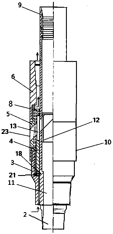
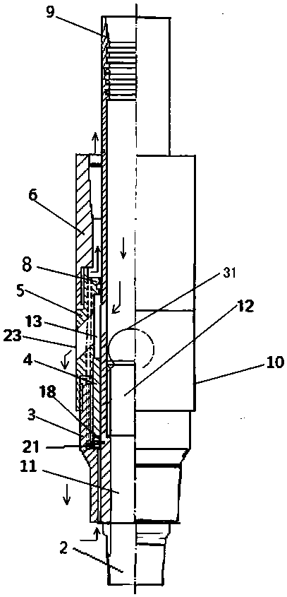
[0026] Embodiment 1, with reference to attached figure 1, an integral layered filling device mentioned in the present invention, its technical solution is: mainly composed of two groups of filling tools 10, sand filter pipe 28, flushing pipe 30 and packer 7, the inner cavity of the filling tool 10 It is connected by flushing pipe 30, and the outer wall is connected by sand filter pipe 28. The upper part of each group of filling tools 10 is provided with a packer 7, and the bottom of the bottom group of filling tools 10 is provided with a blind plug 27. Each group of filling tools 10 is provided with In the corresponding oil layer filling position; wherein, the filling tool 10 includes the lower joint 3 of the filling tool, the sealing sliding sleeve 4, the layered water distribution joint 5, the upper joint 6 of the filling tool, the core tube 11 and the ball seat 12, and the filling The upper joint 6 of the tool and the lower joint 3 of the filling tool are connected with a l...

Embodiment 2

[0040] Embodiment 2, with reference to attached Figure 7 , The difference between the present invention and embodiment 1 is that three sets of filling tools are lowered into the oil well, and the three sets of oil layers are filled in different layers. In specific operation, step three can be repeated to connect and lower the downhole three-component layered filling tool to realize the layered ground filling and ring filling of the three oil layers.

Embodiment 3

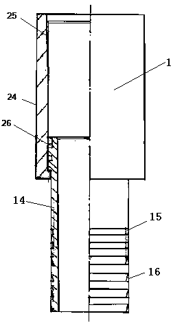
[0041] Embodiment 3, the difference between the present invention and Embodiments 1 and 2 is: the outer wall of the lower part of the inner tube 14 of the present invention is provided with a plurality of snap rings 17, through the snap rings of the inner tube 14 and the next group of filling tools 10 The catcher 9 on the top of the discarding core tube 11 cooperates; the catcher 9 is provided with a plurality of groups of horse teeth buttons corresponding to the snap ring, and the snap ring adopts a circular truncated structure.

[0042] The structure of the present invention can also complete the effective connection and fixation of the hands-free core tube (11) and each group of filling tools (10), and can also play the role of Embodiment 1 or 2.


PUM


Abstract

The invention relates to a construction method of an integral layered filling device. Its technical plan includes the following steps: 1. Lower the pipe string; 2. Carry out the first layer of ground filling and ring filling; put steel balls into the core pipe from the wellhead to establish a liquid circulation channel; then inject liquid from the wellhead and close the Fill the casing valve with sand to the oil layer to complete the ground filling; then open the casing valve and inject the sand-carrying liquid into the core pipe to complete the ring filling; 3. Carry out the second layer of ground filling and ring filling, ground filling and ring filling After the filling is completed, the hand-losing operation is performed; the beneficial effect of the present invention is that the present invention solves the problem that the existing single-layer filling tool cannot be filled in layers, and also overcomes the internal problems in the layered extrusion filling tool of the existing design. The problem of difficult movement of the filling string and the external filling string avoids the problems of switch failure and inaccurate positioning, and realizes the layered ground filling and ring filling of multiple oil layers more easily, which improves the operation efficiency and reduces the cost.

Description

technical field [0001] The invention relates to a construction method of a petroleum workover tool, in particular to a construction method of an integral layered filling device. Background technique [0002] Oil well sand filling is one of the urgent problems to be solved in oilfield development. The main reason for oil well sand production is that the reservoir is loose cemented sandstone. In addition, in the middle and late stages of oilfield development, long-term water injection or gas injection production will also greatly damage the reservoir framework, resulting in sand production in oil wells. The hazards of sand production in oil wells are mainly manifested in three aspects: 1. The sand buries the production layer, causing the oil well to reduce or stop production; Casing damage makes the oil well scrapped, etc. Sand production in oil wells causes a large reduction in oil well production, a sharp increase in operating costs, and serious economic losses. In order ...

Claims


Application Information

Patent Timeline
Patent Type & Authority Patents(China)
IPC IPC(8): E21B43/04
CPCE21B43/04
Inventor 高瑞民
Owner SUZHOU YUANLIAN SCI & TECH PIONEER PARK MANAGEMENT CO LTD
Why Eureka
Try Eureka