
Method for measuring and calculating roughness of field rock structural plane
A calculation method and technology of structural plane, applied in the field of rock mechanics, can solve the problems of unsuitable rock structural plane roughness, less application, etc., and achieve the effect of flexible and convenient method, improving efficiency and accuracy, and reducing deviation
- Summary
- Abstract
- Description
- Claims
- Application Information
AI Technical Summary
Problems solved by technology
Method used
Image

Examples
Embodiment 1
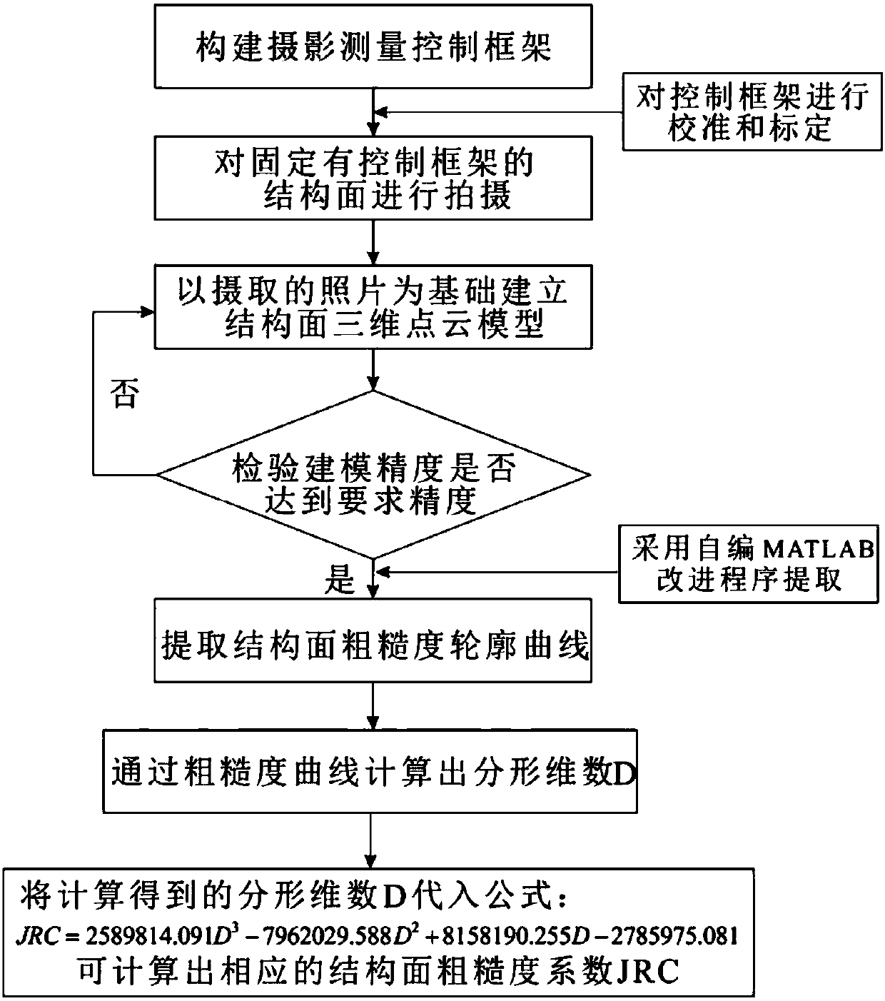
[0048] In this embodiment, the granite rock structural surface in the pre-selected area of Beishan, Gansu Province is taken as the research object, and the measurement and calculation method of the roughness of the rock structural surface in the field is as follows figure 1 shown, including the following steps:
[0049] (1) Build a close-range photogrammetry control framework
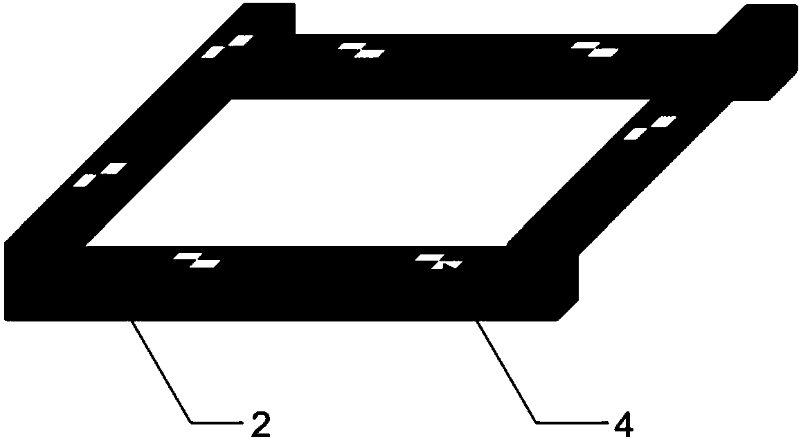
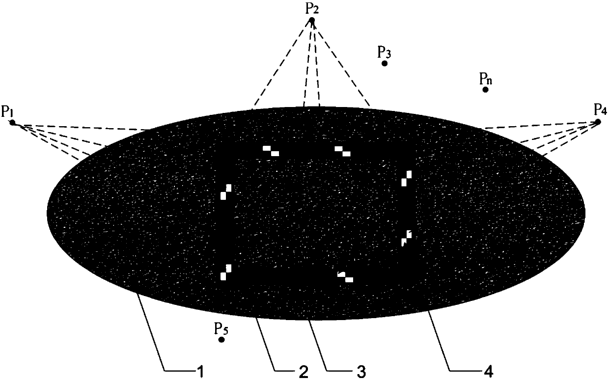
[0050] First, use 4 straight wooden strips with a side length of 50 cm to form a rectangular frame, and then paste 7 photogrammetry mark point labels on the upper surface of the frame to form a control frame, such as figure 2 As shown in Fig. 3, two labels are pasted on each of the three wooden bars, and only one label is pasted on the other. The resulting control frame is calibrated and calibrated indoors with a three-dimensional laser scanner or a total station.
[0051] (2) Calibrate the control frame to meet the set accuracy requirements
PUM
 Abstract
Description
Claims
Application Information