Delayed demolding device for stretching die part

A drawing die and part technology, applied in the field of delayed demoulding equipment for drawing die parts, can solve the problems of high machine tool cost, poor stability, complicated debugging, etc., to ensure production cycle and quality, high reliability, and reduce manufacturing costs. Effect

Inactive Publication Date: 2018-03-06
天津星原汽车零部件有限公司
View PDF7 Cites 1 Cited by
  • Summary
  • Abstract
  • Description
  • Claims
  • Application Information

AI Technical Summary

Problems solved by technology

The former method is expensive for the machine tool and has restrictions on the pressure source of the mold, so only the air cushion of the machine tool can be used; the latter method is only used when the pressure source is a nitrogen cylinder, and the cost is high, the debugging is complicated, and the stability is poor

Method used


Image

  • Delayed demolding device for stretching die part
  • Delayed demolding device for stretching die part
  • Delayed demolding device for stretching die part

Examples


Embodiment Construction

[0020] The present invention will be described in detail below in conjunction with the accompanying drawings.

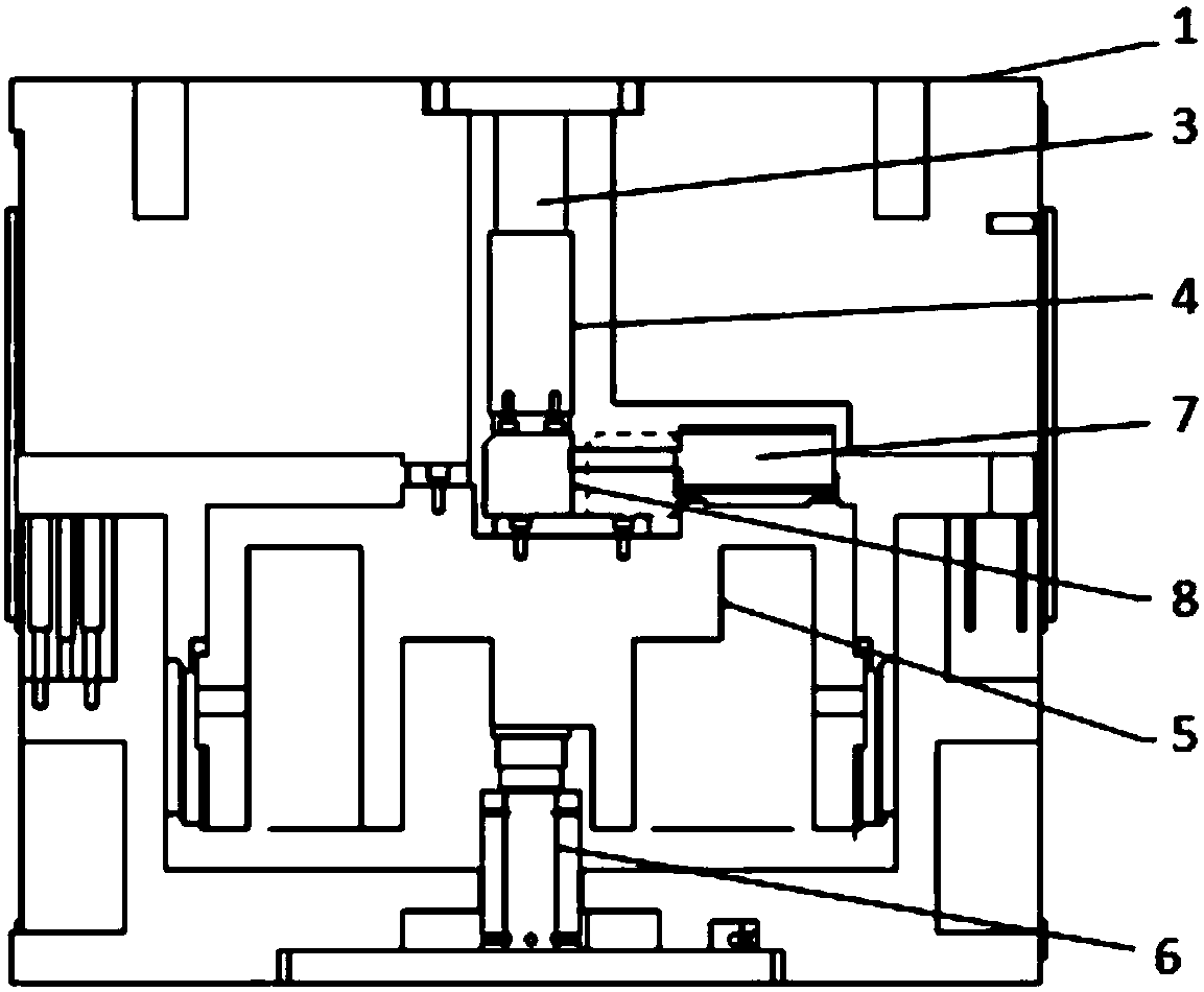
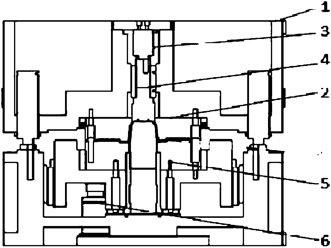
[0021] The problem solved by the present invention is that when the upper die 1 and the die 2 move upwards driven by the upper slider of the machine tool, the lower blank holder 5 moves upwards under the push of the lower nitrogen cylinder 6. At this time, due to the upper pressing core 4 is also pressed on the part, and the lower blankholder 5 will cause upward shape damage to the part that has been stretched.

[0022] like Figure 1-Figure 3 As shown in the schematic diagram of the structure of the present invention, the present invention provides a delayed demoulding device for stretching die parts, comprising an upper die 1 and a die 2, the die 2 is fixed below the upper die 1 by bolts, and the upper die 1 is fixed with an upper nitrogen cylinder 3, the driving end of the upper nitrogen cylinder 3 is connected vertically downward with an upper binder core 4, and...


PUM


Abstract

The invention provides a delayed demolding device for a stretching die part. The delayed demolding device for the stretching die part comprises an upper die body and a female die body; the female diebody is fixed below the upper die body through a bolt; an upper nitrogen cylinder is fixed above the upper die body; the driving end of the upper nitrogen cylinder is vertically and downwardly connected with an upper material pressing core; a lower edge pressing ring is arranged below the female die body; a lower nitrogen cylinder is arranged below the lower edge pressing ring; a demolding mechanism is arranged above the lower edge pressing ring, and comprises a push-pull cylinder fixed to the lower edge pressing ring; and the output end of the push-pull cylinder is connected with an embeddingblock which is embedded between the upper material pressing core and the lower edge pressing ring through a lower guiding plate and a cover plate fixed to the lower edge pressing ring. The delayed demolding device for the stretching die part has the beneficial effect that the problems that a traditional manner is narrow in application range, high in manufacturing cost, and large in debugging difficulty. The structure is simple, installing and debugging are convenient, cost is low, reliability is high, the production period and quality of the die are effectively guaranteed, and the manufacturing cost is reduced.

Description

technical field [0001] The invention belongs to the technical field of sheet metal stamping manufacturing, and in particular relates to a delayed demoulding device for drawing die parts. Background technique [0002] During stamping and stretching, especially when the lower mold has a blank holder outside the punch parting line, and the upper mold has a pressing core inside the punch parting line, the upper pressing core does not move temporarily, and it is necessary to prevent the pressing The destructive deformation of the parts caused by the rise of the edge ring is used to obtain qualified stretched parts. There are two traditional ways to solve this problem: the delay function of the stamping machine tool, and the delay system of the nitrogen cylinder. The former method is expensive for the machine tool and has restrictions on the pressure source of the mold, so only the air cushion of the machine tool can be used; the latter method is only used when the pressure sourc...

Claims


Application Information

Patent Timeline
Patent Type & Authority Applications(China)
IPC IPC(8): B21D22/22B21D37/10B21D45/04
CPCB21D22/22B21D37/10B21D45/04
Inventor 焦雷魁张越鹏
Owner 天津星原汽车零部件有限公司
Why Eureka
Try Eureka