Automatic screening part device

A technology for automatic screening and parts, applied in the direction of solid separation, classification, chemical instruments and methods, etc., can solve problems such as negligence, lack of accurate detection of parts, and easy leakage

Active Publication Date: 2018-03-09
YANGZHOU ZHONGKUANG MACHINE CO LTD
View PDF7 Cites 0 Cited by
  • Summary
  • Abstract
  • Description
  • Claims
  • Application Information

AI Technical Summary

Problems solved by technology

In the actual assembly, due to the negligence of the workers, it is easy to miss one of the parts, resulting in incomplete assembly of the parts; especially, if the part is not visible inside the whole part, then the part that is not assembled will be not easy to distinguish
That is to say, if a component leaves the factory without installing one of the parts during assembly, then installing this unqualified component to other equipment to work directly will cause it to fail to work normally.
Moreover, since the missing parts are located inside the component, they are not easy to be noticed by the installer, which easily leads to negligence when checking whether the assembly is standard
In summary, there is a lack of devices for accurately detecting assembled parts in the prior art

Method used


Image

  • Automatic screening part device
  • Automatic screening part device
  • Automatic screening part device

Examples


Embodiment 1

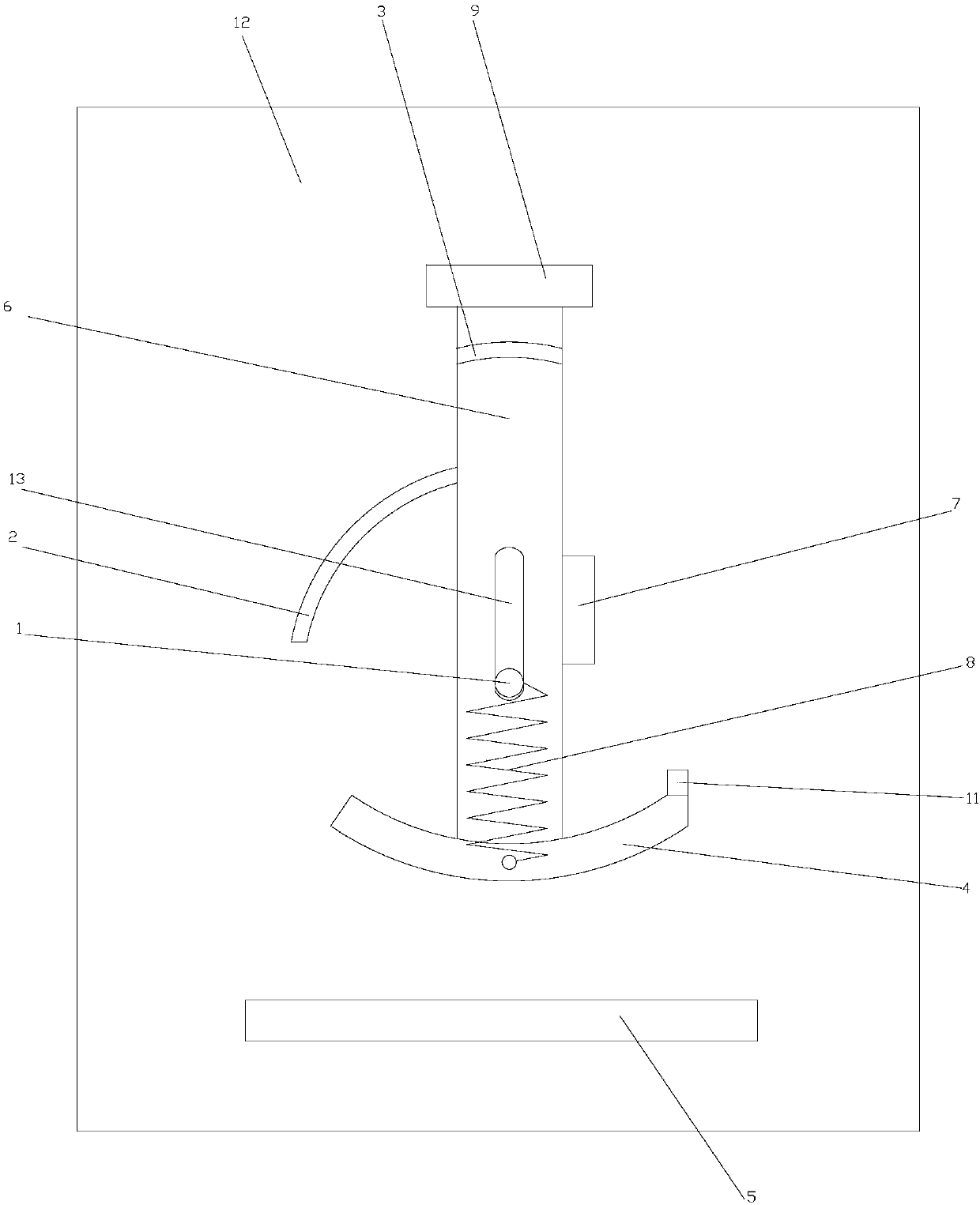
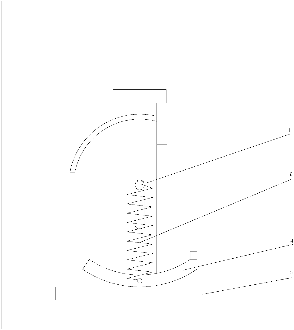
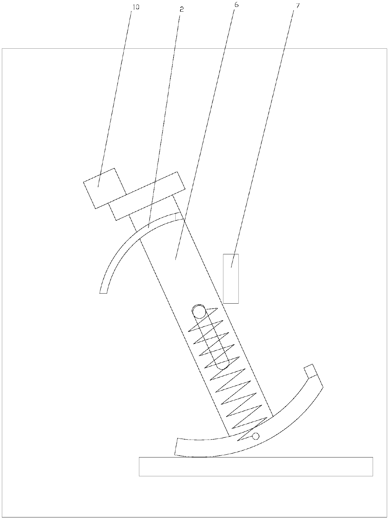
[0018] As shown in the figure, the automatic screening component device of the present invention includes a base 12, a swing plate 6 is rotatably connected to the base 12, a chute 13 is provided on the swing plate 6, a cylindrical pin 1 is arranged on the base 12, and a cylindrical pin 1 Located in the chute 13; the base 12 is respectively provided with a support block 7 and an arc rod 2 on both sides of the pendulum plate 6, the support block 7 is set on the base 12 higher than the cylindrical pin 1, and the arc rod 2 is connected with the cylindrical pin 1 It is arranged on the base 12 for the rotary shaft; the swing plate 6 is provided with an arc-shaped through hole 3 with the cylindrical pin 1 as the rotary shaft, the arc-shaped through-hole 3 and the arc-shaped rod 2 are located on the same vertical plane, and the arc-shaped rod 2 is located on the same vertical plane. 2 Inserted in the arc-shaped through hole 3 or separated from the arc-shaped through hole 3; the upper e...

Embodiment 2

[0023] As shown in the figure, the automatic screening component device of the present invention includes a base 12, a swing plate 6 is rotatably connected to the base 12, a chute 13 is provided on the swing plate 6, a cylindrical pin 1 is arranged on the base 12, and a cylindrical pin 1 Located in the chute 13; the base 12 is respectively provided with a support block 7 and an arc rod 2 on both sides of the pendulum plate 6, the support block 7 is set on the base 12 higher than the cylindrical pin 1, and the arc rod 2 is connected with the cylindrical pin 1 It is arranged on the base 12 for the rotary shaft; the swing plate 6 is provided with an arc-shaped through hole 3 with the cylindrical pin 1 as the rotary shaft, the arc-shaped through-hole 3 and the arc-shaped rod 2 are located on the same vertical plane, and the arc-shaped rod 2 is located on the same vertical plane. 2 Inserted in the arc-shaped through hole 3 or separated from the arc-shaped through hole 3; the upper e...


PUM


Abstract

The invention discloses an automatic screening part device, which comprises a substrate; a swaying plate is rotationally connected to the substrate, and a chute is arranged on the swaying plate; a cylinder pin is arranged on the substrate, and located in the chute; both sides of the substrate at the swaying plate are provided with a supporting block and an arc rod; the supporting block above the cylinder pin is arranged on the substrate, and the arc rod is arranged on the substrate by taking the cylinder pin as a revolving shaft; an arc through hole taking the cylinder pin as the revolving shaft is arranged on the swaying plate, and the arc rod is plugged in the arc through hole or isolated from the arc through hole. The device can automatically judge if the parts after assembly are qualified; the automatic level of the detection device is greatly improved, and the detection work can be carried out continuously; the automatic screening part device can judge if the parts are assembled well through exactly detecting the part weight.

Description

technical field [0001] The invention relates to a device for detecting whether assembly of components is qualified, in particular to an automatic screening device for components. Background technique [0002] During mechanical assembly, multiple parts need to be fitted together to form a component. In the specific assembly, due to the negligence of the workers, it is easy to miss one of the parts, resulting in incomplete assembly of the parts; especially, if the part is not visible inside the whole part, then the part that is not assembled will be Not easy to distinguish. That is to say, if a part leaves the factory without installing one of the parts during assembly, then installing this unqualified part to other equipment to work directly will cause the situation that it cannot work normally. Moreover, since the missing parts are located inside the component, they are not easy to be noticed by the installer, which easily leads to negligence when checking whether the asse...

Claims


Application Information

Patent Timeline
Patent Type & Authority Applications(China)
IPC IPC(8): B07B13/08B07B13/16
CPCB07B13/08B07B13/16
Inventor 许壬强
Owner YANGZHOU ZHONGKUANG MACHINE CO LTD
Why Eureka
Try Eureka