Inflation pump control method and device for air brake electric car

A control method and control device technology, applied in the direction of brake transmission, brakes, vehicle components, etc., can solve the problems of poor control accuracy of air pumps, achieve optimal exhaust time, ensure exhaust time, and promote downtime Effect

Pending Publication Date: 2018-03-20
四川江淮汽车有限公司
View PDF12 Cites 8 Cited by
  • Summary
  • Abstract
  • Description
  • Claims
  • Application Information

AI Technical Summary

Problems solved by technology

[0014] The object of the present invention is: the present invention provides a control method and device for an air brake electric vehicle air pump, which solves the problem that the existing air pump control method is affected by dryers, mechanical pressure regulation and environmental factors, resulting in poor control accuracy of the air pump The problem

Method used


Image

  • Inflation pump control method and device for air brake electric car
  • Inflation pump control method and device for air brake electric car
  • Inflation pump control method and device for air brake electric car

Examples


Embodiment 1

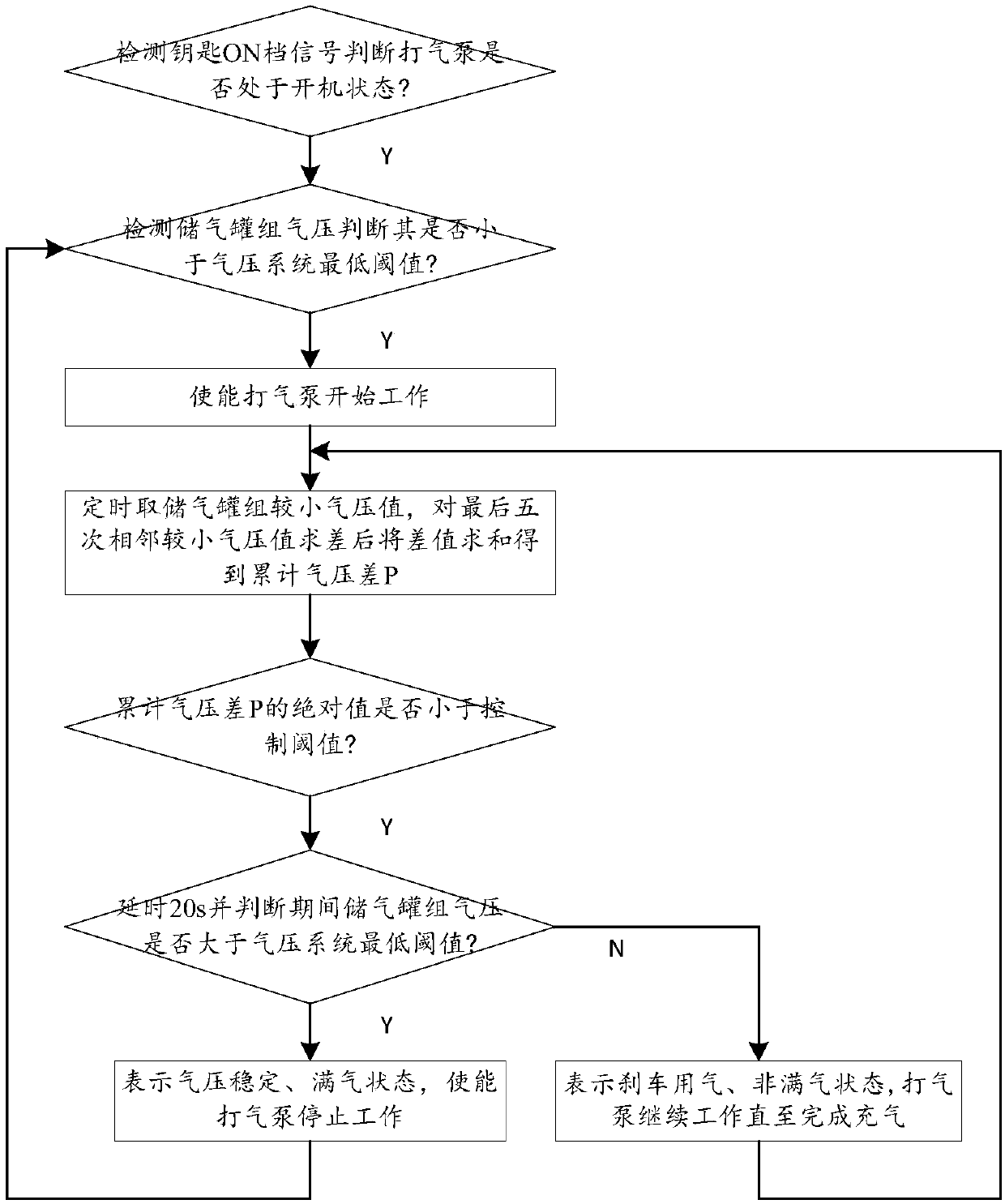
[0047] A method for controlling an air pump for an air brake electric vehicle, comprising the following steps:

[0048] Step 1: Detect the key ON gear signal to determine whether the air pump is on, if so, skip to step 2, otherwise end;

[0049] Step 2: Detect the air pressure of the air storage tank group to determine whether it is lower than the minimum threshold of the air pressure system. If so, enable the air pump to start working and skip to step 3. If not, continue to detect the air pressure of the air storage tank group;

[0050] Step 3: Take the smaller air pressure value of the air storage tank group regularly, calculate the difference of the last five adjacent smaller air pressure values, and then sum the differences to obtain the cumulative air pressure difference P, and skip to step 4;

[0051] Step 4: Determine whether the absolute value of the accumulated air pressure difference P is less than the control threshold. If so, delay for 20s and judge whether the air...

Embodiment 2

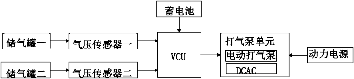
[0065] Working principle: an air pump control device for an air brake electric vehicle, including an air storage tank group, an air pressure sensor group, a VCU, an air pump unit and a power supply; the air pressure sensor group, VCU and the air pump unit are electrically connected in sequence, and the air pressure sensor is set In the gas storage tank; the power supply includes a storage battery and a power supply, the storage battery is electrically connected to the VCU, and the power supply is electrically connected to the air pump unit. The air storage tank group includes air storage tank 1 and air storage tank 2, and the air pressure sensor group includes air pressure sensor 1 and air pressure sensor 2; air pressure sensor 1 and air pressure sensor 2 are electrically connected to the VCU respectively, and the air pump unit includes an electric air pump and a DCAC , the electric air pump, DCAC and power supply are electrically connected in sequence, and the VCU is electrica...


PUM


Abstract

The invention discloses an inflation pump control method and device for an air brake electric car, and relates o the field of inflation pump control methods. The inflation pump control method includes: determining if an inflation pump is in a starting up state or not; detecting the air pressure, determining if the air pressure is less than a lowest threshold or not, regularly measuring small air pressure values of an air storage tank set after the inflation pump starts working if so; differencing last five adjacent small air pressure values, and summing the differences to acquire an accumulative air pressure difference P; determining if an absolute value of the accumulative air pressure difference P is less a control threshold or not, and delaying 20 s and determining if the air pressure of the air storage tank set is greater than the lowest threshold or not during the period if so; allowing the inflation pump to stop working if so and jumping to air pressure detection; and allowing the inflation pump to work continuously if not till inflation is completed. The problem that the conventional inflation pumps are influenced by factors such as dryers, mechanical pressure adjustment andenvironments and result in poor control precision can be solved; stop is determined according to a stabile pressure, and the defects of poor control precision of the inflation pumps due to the fact the prior art is influenced by various factors can be overcome.

Description

technical field [0001] The invention relates to the field of air pump control methods, in particular to an air brake electric vehicle air pump control method and device. Background technique [0002] At present, the braking system of air brake electric vehicles generally replaces the electronic air pump on the basis of the original fuel vehicle. In order to save electric energy, other electronic devices detect the system air pressure to control the start and stop of the air pump; The air pump works, and when the air pressure is higher than the minimum threshold, the air pump stops (or stops after a delay); with the current control method, since the dryer in the air brake system needs to perform exhaust blowback for a certain period of time (this process is accompanied by system Air pressure drops), leading to poor control of the maximum threshold value and delay time, it is easy to cause insufficient or no backflushing time of the dryer or too long backflushing time, resulti...

Claims


Application Information

Patent Timeline
Patent Type & Authority Applications(China)
IPC IPC(8): B60T13/26B60T13/66B60T17/22
CPCB60T13/26B60T13/66B60T17/22
Inventor 蒋大伟赵虎任佩红马其鼎柏剑何艺吴怀述罗明勇伍藻君
Owner 四川江淮汽车有限公司
Why Eureka
Try Eureka