Novel dehumidifier low-temperature defrosting method

A dehumidifier and low temperature technology, applied in the field of low-temperature defrosting of new dehumidifiers, can solve the problems of inability to remove the frost, waste power and energy, and fail to achieve the defrosting effect, and achieve the effect of improving the defrosting efficiency and avoiding the waste of resources.

Pending Publication Date: 2021-11-05
宁波德业日用电器科技有限公司
View PDF6 Cites 1 Cited by
  • Summary
  • Abstract
  • Description
  • Claims
  • Application Information

AI Technical Summary

Problems solved by technology

[0002] When the refrigerated dehumidifier works in a low-temperature environment, as the working time prolongs, more and more frost will hang on the evaporator. In severe cases, the ventilation gap of the evaporator is almost completely blocked, resulting in a decrease in the working efficiency of the dehumidifier. , wasting electrical energy
In order to improve this problem, the current mainstream technology in the dehumidifier industry adopts the accumulative defrosting technology of a single temperature section. In this method, no matter whether the ambient temperature is high or low, the shutdown time of the compressor and the accumulative defrosting The cycle of frost is fixed, which will appear: 1. When the temperature is high, there will be less frost on the evaporator, and the machine only needs to shut down the compressor for a very short time, and the frost can be removed by the high-speed operation of the fan clean, but the compressor is still off at this time, and does not start to enter the dehumidification work, resulting in low dehumidification efficiency of the dehumidifier
2. When the temperature is low or the humidity is high, the time when the compressor is shut down is too short, and the machine cannot completely remove the frost through the high-speed operation of the fan, and the expected defrosting effect cannot be achieved.

Method used


Image

  • Novel dehumidifier low-temperature defrosting method

Examples


Embodiment 1

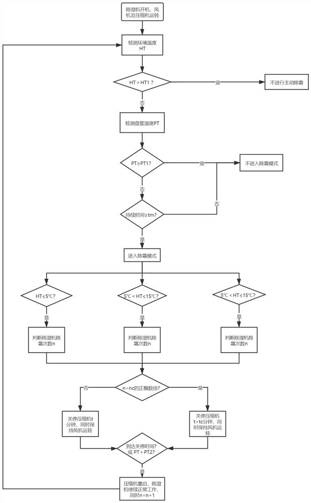
[0017] The novel dehumidifier low-temperature defrosting method described in this embodiment, such as figure 1 As shown, it includes the following steps:

[0018] a. Detect the ambient temperature HT; judge whether the dehumidifier needs to perform active defrosting according to the ambient temperature HT, and if the ambient temperature HT is greater than the first preset ambient temperature HT1, the dehumidifier will not perform active defrosting; in step a of this embodiment , the reason for not performing active defrosting is that when HT>HT1, it can be considered that at this ambient temperature HT, frost will not occur on the surface of the evaporator or the frost will inevitably melt within a predetermined time after frosting. In actual operation, it can be determined through experiments. In this embodiment, 25° C. is used as the first preset temperature HT1 , that is, HT1 = 25° C.

[0019] b. When the ambient temperature HT1 is less than or equal to the first environme...


PUM


Abstract

The invention discloses a novel dehumidifier low-temperature defrosting method which comprises the steps of detecting an environment temperature HT, judging whether a dehumidifier needs to be subjected to active defrosting or not according to the environment temperature HT, judging whether the dehumidifier needs to enter a defrosting mode or not according to a temperature PT of a coil pipe and a duration tm, deciding a shutdown time t of a compressor according to a preset temperature interval and the number n of defrosting times performed by the dehumidifier, keeping a fan to operate for defrosting at the same time, and finally, judging whether the compressor is restarted to recover normal work or not according to the temperature of the coil pipe or the shutdown time. According to the novel dehumidifier low-temperature defrosting method disclosed by the invention , by setting four temperature sections, namely three temperature intervals with the temperature larger than a first preset temperature and a maximum end value smaller than or equal to the first preset temperature, the shutdown time of the compressor is controlled precisely in a targeted mode, so that resource waste caused by long or too short shutdown time of the compressor in a single temperature section method is avoided, and the defrosting efficiency and the dehumidification efficiency of the dehumidifier are obviously improved.

Description

technical field [0001] The invention relates to a low-temperature defrosting method for a dehumidifier, in particular to a novel low-temperature defrosting method for a dehumidifier. Background technique [0002] When the refrigerated dehumidifier works in a low-temperature environment, as the working time prolongs, more and more frost will hang on the evaporator. In severe cases, the ventilation gap of the evaporator is almost completely blocked, resulting in a decrease in the working efficiency of the dehumidifier. , wasting electrical energy. In order to improve this problem, the current mainstream technology in the dehumidifier industry adopts the accumulative defrosting technology of a single temperature section. In this method, regardless of whether the ambient temperature is high or low, the shutdown time of the compressor and the accumulative defrosting The cycle of frost is fixed, which will appear: 1. When the temperature is high, there will be less frost on the e...

Claims


Application Information

Patent Timeline
Patent Type & Authority Applications(China)
IPC IPC(8): F24F11/41F24F11/64F24F11/65F24F11/86F24F11/77F24F11/61
CPCF24F11/41F24F11/64F24F11/65F24F11/86F24F11/77F24F11/61Y02B30/70
Inventor 张栋业姚嘉毅张和君叶盛华
Owner 宁波德业日用电器科技有限公司
Why Eureka
Try Eureka