Air source heat pump drying house with air inlet of evaporator as fresh air inlet of drying house

An air source heat pump and air inlet technology, applied in heat pumps, dryers, dryers, etc., can solve problems such as low energy efficiency ratio, meaningless cooling and dehumidification of evaporators, inability to dehydrate air, etc., and achieve high energy efficiency ratio, which is beneficial to The effect of dehumidification

Inactive Publication Date: 2015-02-18
湖南省浏阳市择明热工器材有限公司
View PDF6 Cites 21 Cited by
  • Summary
  • Abstract
  • Description
  • Claims
  • Application Information

AI Technical Summary

Problems solved by technology

[0007] Compared with the following dehumidification type, the energy efficiency ratio of the dehumidification type is much improved, but its disadvantages are: 1) Even if the waste heat is recovered, only about 35% can be recovered, and a large amount of heat is still discharged. Outside the drying room, a lot of energy is wasted; 2) During the entire drying process of materials, the dehumidification effect (dehumidification rate) of the dehumidification type is much worse than that of the dehumidification type; 3) The fresh air for dehumidification and supplementation comes from the air in the environment without dehumidification treatment; the above three shortcomings reduce the drying speed of materials
[0009] The disadvantages of this technical solution are: 1) When the material in the drying room is initially heated, it is meaningless to cool and dehumidify the evaporator, because the temperature difference between the air temperature in the drying room and the ambient temperature is small, and the air in the drying room cannot reach the dew point for dehydration
On the contrary, due to the cooling of the evaporator, the initial heating time of the material in the drying room is significantly prolonged
2) The air source heat pump fan operates in a sealed or relatively sealed environment and cannot absorb heat from the external environment. A large part of the heating energy of the heat pump is offset by the condensation and dehumidification of the evaporator, and the energy efficiency ratio is only about 1.0. The energy efficiency ratio is too low, the material heating and temperature rise speed is slow, the drying effect is only slightly better than that of the resistance type drying room, and the advantages of high-efficiency heating of the air source heat pump are not utilized, and the drying speed of the material is not as good as that of the dehumidification type air source heat pump drying room

Method used


Image

  • Air source heat pump drying house with air inlet of evaporator as fresh air inlet of drying house

Examples


Embodiment Construction

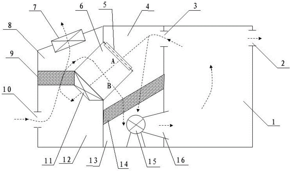
[0038] Referring to the accompanying drawings, reflecting a specific structure of the present invention, the air source heat pump drying room with the air inlet of the evaporator as the new air outlet of the drying room includes an air source heat pump, a drying room 1 and a total heat heat exchanger 6, the described The casing of the air source heat pump is divided into a first inner cavity and a second inner cavity that are independent of each other:

[0039] The first inner chamber is divided into X chamber 8 and Y chamber 12 by evaporator 9, Y chamber 12 is provided with air inlet 10, X chamber 8 is provided with air outlet of device evaporator fan 7;

[0040] The second inner cavity is divided into an air inlet chamber 4 and an air outlet chamber 13 by a condenser 14; the air outlet chamber 13 is equipped with a condenser fan 15 and is connected to the air inlet 16 of the drying room; the air inlet chamber 4 is connected to the return air outlet 3 of the drying room 1 ; A...


PUM


Abstract

The invention discloses an air source heat pump drying house with the air inlet of an evaporator as the fresh air inlet of a drying house. The air source heat pump drying house comprises an air source heat pump, the drying house and an air-to-air total heat exchanger, and the housing of the air source heat pump is divided into a first chamber and a second chamber. When an automatic air door is closed, under the function of a condenser fan, relatively closed circulating air is generated to heat the drying house; when the temperature of material in the drying house is increased to certain temperature and humidity is increased, the automatic air door is opened, so that the air inlet of the evaporator serves as the fresh air inlet of the drying house. With the overall system structure configuration and the utilization of cold air after the heat exchange of the evaporator as a basis and the opening and closing of the automatic air door as a switching condition, the material drying method in which dehumidification and moisture removal are carried out at the same time is innovated, thus realizing the organic combination of a variety of operating modes; the overall functional trend of the system can be automatically, flexibly and conveniently changed to meet the different and even contradictory requirements of all material drying stages; the great increases of both energy efficiency ratio and material drying speed can be taken into consideration; equipment investment is saved.

Description

technical field [0001] The invention relates to an air source heat pump drying room for material drying. Background technique [0002] Material drying generally uses air as the heating medium to heat the material with heat energy higher or significantly higher than the temperature of the material. The heated air contacts the surface of the material, the hot air cools down, and the temperature of the material absorbs heat rises. After the material is heated, From the surface to the inside, the water absorbs heat and evaporates or vaporizes. The water molecules and the heating medium become hot and humid air, and the dehumidification fan is discharged out of the drying room. [0003] The air source heat pump is mainly composed of a condenser, a condenser fan, a compressor, a throttling device, an evaporator, and an evaporator fan. loop loop. [0004] The air source heat pump drying room has been widely used in people's production activities. There are mainly two types of dry...

Claims


Application Information

Patent Timeline
Patent Type & Authority Applications(China)
IPC IPC(8): F26B9/06F26B21/00F25B30/06
Inventor 汤世国
Owner 湖南省浏阳市择明热工器材有限公司
Why Eureka
Try Eureka