Steam-water separation equipment

A steam-water separation and steam-water separator technology, applied in mechanical equipment, steam traps, etc., can solve the problems of equipment safety or efficiency impact, low separation efficiency, and failure to reach the dryness of high-pressure cylinder equipment, so as to improve efficiency, Increase the contact area and ensure the effect of reliable operation

Active Publication Date: 2017-12-22
DONGFANG (GUANGZHOU) HEAVY MASCH CO LTD
View PDF6 Cites 3 Cited by
  • Summary
  • Abstract
  • Description
  • Claims
  • Application Information

AI Technical Summary

Problems solved by technology

[0003] In the existing technology, a simple steam-water separation device is directly installed in the pipeline. The separation efficiency is not high, and the dryness required by the follow-up equipment of the high-pressure cylinder cannot be achieved, which seriously affects the safety or efficiency of the equipment.

Method used


Image

  • Steam-water separation equipment
  • Steam-water separation equipment
  • Steam-water separation equipment

Examples


Embodiment Construction

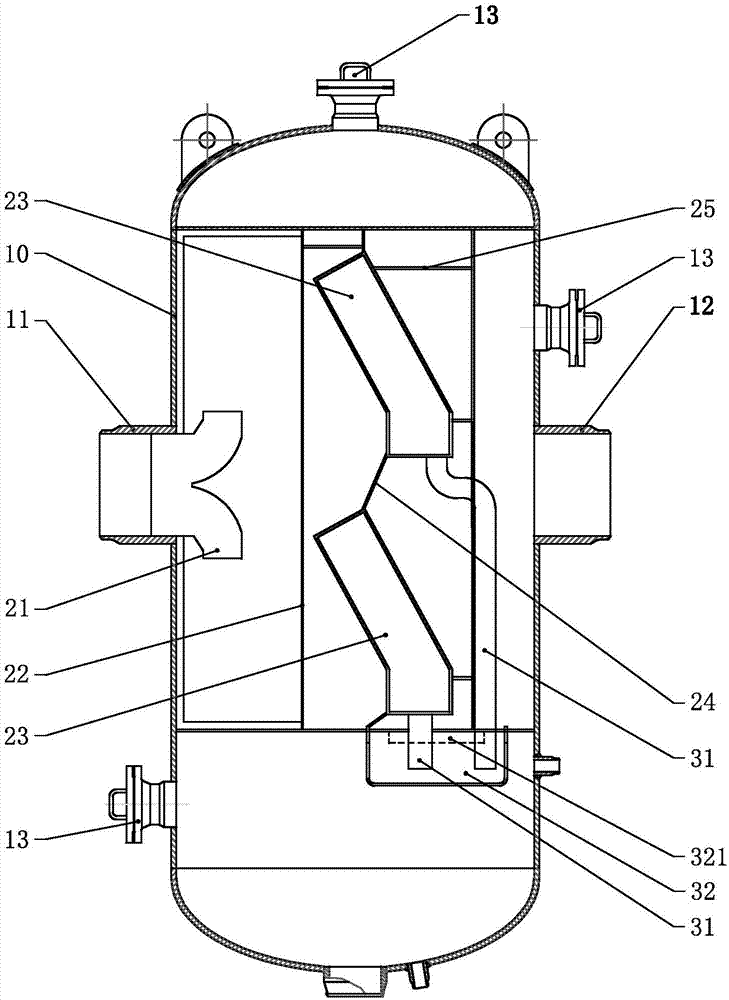
[0017] refer to Figure 1 to Figure 5 , a steam-water separation device in this embodiment, the device includes a cylinder 10, the side wall of the cylinder 10 is respectively symmetrically provided with a steam inlet 11 and a steam outlet 12, and the lower part of the cylinder 10 is fixedly equipped with two supporting feet 14. The support foot 14 and the anchor piece 15 are connected by bolts to fix the steam-water separation device. A steam-water separation cavity is formed inside the cylinder 10, and a flow distributor and a steam-water separator are respectively fixedly installed in the steam-water separation cavity. Under the action of the flow distributor, the steam flowing in from the steam inlet 11 enters the steam-water separation evenly The steam-water separator includes two steam-water separation units 23 distributed in the upper and lower layers. The steam-water separation unit 23 is obliquely fixed in the steam-water separation chamber through a fixed bracket 25,...


PUM


Abstract

Steam-water separation equipment comprises a barrel with a steam-water separation cavity. The steam-water separation cavity comprises a flow distributor and a steam-water separator which communicate with each other in sequence. A steam inlet communicating with the flow distributor and a steam outlet communicating with the steam-water separator are formed in the side wall of the barrel. The steam-water separator comprises a plurality of obliquely arranged steam-water separation units, the steam-water separation units are arranged longitudinally, and a connecting plate is connected between the end portions of every two adjacent steam-water separation units. By obliquely arranging the steam-water separation units, the contact area of steam and the steam-water separation units is effectively enlarged, and the steam-water separation efficiency is improved. Besides, as the steam-water separation units are disposed layer by layer longitudinally, the problem that the height of a single steam-water separation unit is limited is solved, and meanwhile by adoption of the layering arrangement mode, the steam entry amount and the drainage volume of each steam-water separation unit can be reduced, and reliable running of the steam-water separation units is ensured.

Description

technical field [0001] The invention relates to the technical field of nuclear power engineering, in particular to a steam-water separation device. Background technique [0002] In a nuclear power plant, the steam entering the steam turbine is saturated steam, so the humidity of the steam discharged from the high-pressure cylinder after doing work is relatively high. However, a series of equipment located behind the high-pressure cylinder has high requirements on dryness, so it is necessary to reduce the humidity of the steam discharged from the high-pressure cylinder. In order to reduce the humidity of the steam, the steam-water separation equipment is used to separate the steam from the wet steam, so as to improve the dryness of the wet steam. [0003] In the existing technology, a simple steam-water separation device is directly installed in the pipeline. The separation efficiency is not high, and the dryness required by the follow-up equipment of the high-pressure cylin...

Claims


Application Information

Patent Timeline
Patent Type & Authority Applications(China)
IPC IPC(8): F16T1/00F16T1/38
Inventor 刘亮亮邱善文王巍周丹伍龙燕
Owner DONGFANG (GUANGZHOU) HEAVY MASCH CO LTD
Why Eureka
Try Eureka