Foundation pit engineering three-dimensional monitoring network realization method based on distributed optical fiber sensors

A distributed optical fiber and optical fiber sensor technology, applied in the field of geotechnical engineering and foundation pit engineering monitoring, can solve the problems of large accidental errors, many manual operations, single-point monitoring, etc.

Active Publication Date: 2018-03-27
TONGJI UNIV
View PDF6 Cites 31 Cited by
  • Summary
  • Abstract
  • Description
  • Claims
  • Application Information

AI Technical Summary

Problems solved by technology

At present, the commonly used deformation monitoring methods include levels and inclinometers, etc., but due to the large accidental errors caused by human factors, scattered data points are difficult to truly reflect the overall deformation of the structure, which belongs to point monitoring. Most of the technology is limited to the monitoring of a single enclosure structure, with more manual operations, single-point monitoring, and no real-time monitoring and feedback system

Method used


Image

  • Foundation pit engineering three-dimensional monitoring network realization method based on distributed optical fiber sensors
  • Foundation pit engineering three-dimensional monitoring network realization method based on distributed optical fiber sensors
  • Foundation pit engineering three-dimensional monitoring network realization method based on distributed optical fiber sensors

Examples


Embodiment

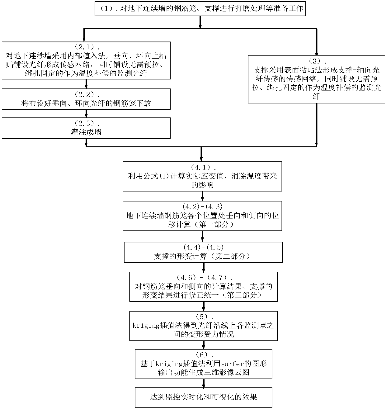
[0065] The invention provides a method for realizing a three-dimensional monitoring network of foundation pit engineering based on distributed optical fiber sensors. (The implementation steps are as follows figure 1 shown, where the number label is the order of the steps)

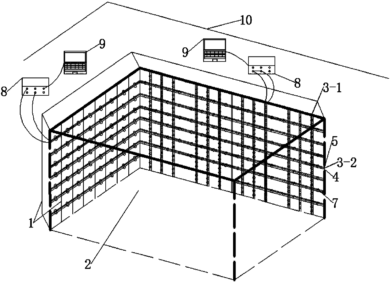
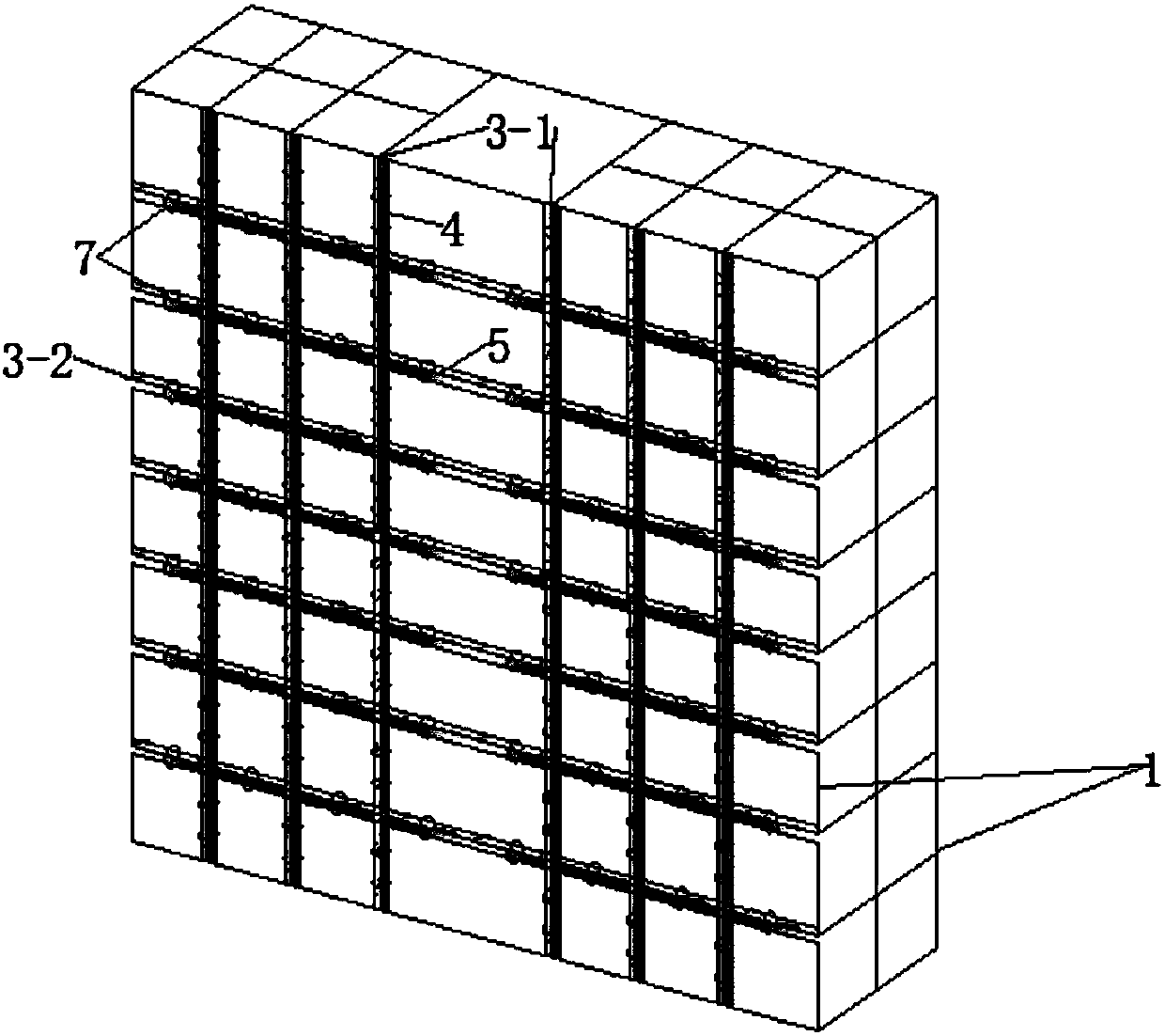
[0066] (1). Before the steel cage 1 of the underground diaphragm wall is lowered, the steel bars are polished to remove the sharp parts on the surface, so as to reduce unnecessary damage to the optical fiber sheath.

[0067] (2). In the reinforcement cage 1 of the underground diaphragm wall, the sensing optical fiber 4 for monitoring the strain and the sensing optical fiber 5 as temperature compensation are arranged. The arrangement of the sensing optical fibers 4 and 5 adopts the internal implantation method, mainly for the reinforcement cage 1 Lay sensing optical fibers 4 and 5 on the two sides facing and facing away from the foundation pit area, and lay the sensing fibers 4 and 5 on the two sides of the...


PUM


Abstract

The invention provides a foundation pit engineering three-dimensional monitoring network realization method based on distributed optical fiber sensors, which relates to a scheme of laying optical fiber sensors on an enclosure and support structure, overall deformation and force bearing analysis on the enclosure and support structure and generation of a strain distribution cloud map. Based on the characteristics that the frequency changes of back Brillouin scattering light formed by scattering of optical wave molecules of the optical fibers and incident light are sensitive to strain and temperature and BOTDA sensing advantages and benefiting from the accurate, stable and real-time monitoring advantages of the optical fiber sensors, the optical fibers on the components are arranged to a three-dimensional monitoring network, comprehensive and three-dimensional deformation and force bearing monitoring can be carried out on enclosure and support components and other components in the foundation pit project, real-time monitored data are guided to surfer to generate a structure strain distribution cloud map, and the method of the invention is a visualized and three-dimensional monitoringmeasurement and control method.

Description

technical field [0001] The invention belongs to the technical field of geotechnical engineering and foundation pit engineering monitoring, and in particular relates to a method for realizing a three-dimensional monitoring network of foundation pit engineering based on distributed optical fiber sensors. Background technique [0002] The stability of deep foundation pit itself and its impact on surrounding buildings during excavation and support are important issues in foundation pit engineering. The deformation monitoring of the foundation pit project runs through the stages before, during and after the implementation of the project, which is a necessary work to evaluate the stability of the foundation pit and the degree of influence on the surrounding buildings. At present, the commonly used deformation monitoring methods include levels and inclinometers, etc., but due to the large accidental errors caused by human factors, scattered data points are difficult to truly reflec...

Claims


Application Information

Patent Timeline
Patent Type & Authority Applications(China)
IPC IPC(8): G01B11/16
CPCG01B11/16
Inventor 王建秀崔韬刘笑天赵宇徐娜邓沿生刘月圆
Owner TONGJI UNIV
Why Eureka
Try Eureka