Screw compressor economizer plenum for pulsation reduction

A technology for compressors and economizers, which is applied to independent rotary compressors, irreversible cycle compressors, compressors, etc., can solve problems such as pulsation propagation at the mouth of the economizer

Active Publication Date: 2021-01-22
CARRIER CORP
View PDF10 Cites 0 Cited by
  • Summary
  • Abstract
  • Description
  • Claims
  • Application Information

AI Technical Summary

Problems solved by technology

[0005] A significant problem with this type of compressor is the propagation of pulsations from the economizer port

Method used


Image

  • Screw compressor economizer plenum for pulsation reduction
  • Screw compressor economizer plenum for pulsation reduction
  • Screw compressor economizer plenum for pulsation reduction

Examples


Embodiment Construction

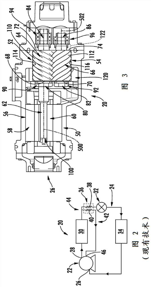
[0038]figure 2 A vapor compression system 20 with a compressor 22 along the recirculation refrigeration flow passage 24 is shown. For illustrative purposes, the exemplary system 20 is the most basic system. Many changes are known or may be yet to be developed. Along the flow path 20, the compressor 22 has a suction port (inlet) 26 and a discharge port (outlet) 28. In the normal operation mode, the refrigerant sucked in through the suction port 26 is compressed at a high pressure from the discharge port 28 and discharged to travel to the downstream side along the flow passage 24 and finally returns to the suction port. The sequence from upstream to downstream along the flow path 24 is: heat exchanger 30 (heat rejection heat exchanger in normal mode); expansion device 32 (for example, electronic expansion valve (EXV) or thermal expansion valve (TXV)); and Heat exchanger 34 (a heat-absorbing heat exchanger in the normal mode). Depending on the specific task involved, the exchanger can ...


PUM


Abstract

A compressor (22) has a male rotor (52), a female rotor (54), and a housing (50). The housing has a first bore (114) and a second bore (116) respectively accommodating portions of the male rotor and the female rotor. The housing has an inlet (26), an outlet (28), an economizer port (150) along at least one of the first bore and the second bore, and an external port (46) communicating with the economizer port. The housing has a chamber (152) between the economizer port and the external port having a volume of at least 0.8 liter.

Description

[0001]Cross reference of related applications[0002]This application claims the benefit of U.S. Patent Application No. 62 / 203,858, filed on August 11, 2015 and entitled "Screw Compressor Economizer Plenum for Pulsation Reduction". The disclosure of the U.S. Patent Application is incorporated by reference in its entirety as detailed Into this article.Background technique[0003]The present disclosure relates to compressors. More specifically, the present disclosure relates to energy-saving compressors.[0004]Positive displacement compressors such as screw compressors are commonly used in applications such as chillers. Many of these compressors are energy-efficient, with an economizer port between the suction port and the discharge port. During the operation of the cooler compressor, the economizer flow bypasses the main flow and is used to absorb heat from the main flow before returning to the economizer port. This expands the range of compressor and system operations.[0005]A significant...

Claims


Application Information

Patent Timeline
Patent Type & Authority Patents(China)
IPC IPC(8): F04C18/16
CPCF04C18/16F25B1/10F25B3/00F25B9/145F25B39/04F25B45/00F25B2400/13F25B2500/12F25B2500/13
Inventor A.维亚D.M.罗克韦尔P.J.皮雷斯基
Owner CARRIER CORP
Why Eureka
Try Eureka