Terminal and terminal battery control method

A battery and terminal technology, applied in the direction of battery load switching, battery circuit device, safety/protection battery circuit, etc., can solve the problems of performance differentiation, affecting user experience, battery power consumption, etc., to avoid the effect of mutual charging

Inactive Publication Date: 2018-03-30
NUBIA TECHNOLOGY CO LTD
View PDF5 Cites 3 Cited by
  • Summary
  • Abstract
  • Description
  • Claims
  • Application Information

AI Technical Summary

Problems solved by technology

[0003] At present, when using the parallel battery solution, the manufacturer will strictly select two batteries with the same specifications and performance to be paralleled to form a parallel battery. However, as the usage time increases, the performance of the two parallel batteries will vary. For example, battery A discharges quickly. , B battery discharges slowly, during the discharge process, A battery will charge B battery, such a cycle of charging will lead to rapid consumption of battery power, reduce user use time, and affect user experience

Method used


Image

  • Terminal and terminal battery control method
  • Terminal and terminal battery control method
  • Terminal and terminal battery control method

Examples


Embodiment Construction

[0028] It should be understood that the specific embodiments described here are only used to explain the present invention, not to limit the present invention.

[0029] In the following description, use of suffixes such as 'module', 'part' or 'unit' for denoting elements is only to facilitate description of the present invention and has no specific meaning by itself. Therefore, 'module', 'part' or 'unit' may be used in combination.

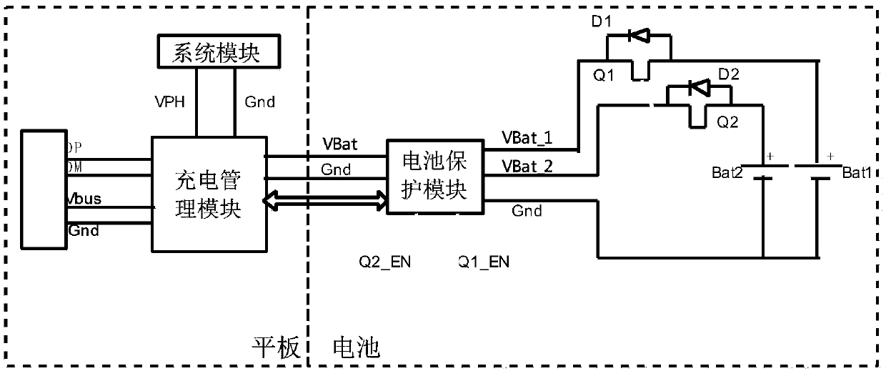
[0030] Such as figure 1 As shown, an embodiment of the present invention provides a terminal. Multiple batteries connected in parallel are installed in the terminal in this embodiment, so the terminal in the embodiment includes but is not limited to a tablet computer or a large-sized mobile phone.

[0031] In this embodiment, there is no limit to the number of batteries ( figure 1 Although there are only 2 batteries in the model, more batteries can actually be installed).

[0032] The terminal includes a system module 110, a charging management...


PUM


Abstract

The invention discloses a terminal and a terminal battery control method. Multiple batteries connected in parallel are mounted in the terminal; the terminal comprises a system module, a charging management module, a battery protection module, a plurality of switches, and a plurality of one-way conductive devices; the battery protection module has multiple first pins; each first pin is connected toone switch and one one-way conductive device, and the switches and the one-way conductive devices are connected to the positive electrode of one battery; the battery protection module has a groundingpin connected to the negative electrodes of multiple batteries; the switches and the one-way conductive devices are connected in parallel; the one-way conductive devices control the positive electrodes of the corresponding batteries to perform one-way electric conduction on the corresponding first pins; the battery protection module has multiple second pins; and each second pin is connected to one switch. According to the technical scheme disclosed in the invention, by virtue of existence of the one way conductive devices, each battery can only supply power without being charged, so that a condition of mutual charging between the batteries can be avoided.

Description

technical field [0001] The invention relates to the technical field of battery charging and discharging, in particular to a terminal and a terminal battery control method. Background technique [0002] With the development of science and technology, smart phones have become the center of personal information, tablet computers meet everyone's mild entertainment needs such as Internet access, games, and videos, and PCs (personal computers) are responsible for office duties. Although individual products are becoming more and more powerful in function, the boundaries in form are becoming more and more blurred. Digital products are becoming more and more scene-oriented rather than functional. Large and comprehensive products are being extremely demanded, and the requirements for batteries are also getting higher and higher. Take a tablet computer as an example, the size of the tablet computer is large, so the power consumption is high. In order to meet the demand of the market, ...

Claims


Application Information

Patent Timeline
Patent Type & Authority Applications(China)
IPC IPC(8): H02J7/00
CPCH02J7/0026H02J7/0063H02J7/0068
Inventor 蒋权
Owner NUBIA TECHNOLOGY CO LTD
Why Eureka
Try Eureka