Multi-functional thermal printing machine

A thermal printer, multi-functional technology, applied in the field of printing and thermal printing machinery, can solve the problem of single function of thermal printer

Inactive Publication Date: 2018-04-03
宋晓月
View PDF0 Cites 0 Cited by
  • Summary
  • Abstract
  • Description
  • Claims
  • Application Information

AI Technical Summary

Problems solved by technology

[0003] In order to solve the problem of single function of thermal printing machine, the present invention designs an integrated machine that can simultaneously complete screen printing and thermal printing

Method used


Image

  • Multi-functional thermal printing machine
  • Multi-functional thermal printing machine

Examples


Embodiment Construction

[0014] The present invention will be further described below in conjunction with the accompanying drawings and embodiments.

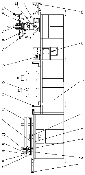
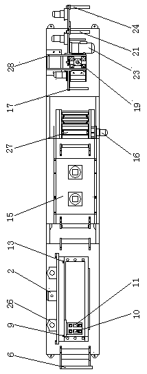
[0015] As shown in the figure, a screen printing mechanism is installed on the upper left of the bottom box 1, a thermal printing mechanism is installed on the right, an oven 15 is installed in the middle, a servo motor 16 is installed on the right side of the oven 15, and a servo motor 16 is installed on the right side. Strip driving roller 27 (top view) is housed, and the front of strip driving roller 27 is equipped with strip storage material slide block.

[0016] The screen printing mechanism on the left includes a screen printing workbench on the bottom box 1, a vertical screen printing support cylinder 2 on the screen printing workbench, a silk screen support 7 on the guide shaft of the screen printing support cylinder 2, and a silk screen support 7 at the bottom of the screen printing support. Screen printing plate 12, rodless cylinder 8 is equip...


PUM


Abstract

A multi-functional thermal printing machine, which is characterized in that a screen printing mechanism is installed on the upper left of the bottom box, a thermal printing mechanism is installed on the right, an oven is installed in the middle, a servo motor is installed on the right side of the oven, and a servo motor is installed on the right The side is equipped with a strip drive roller, and the front of the belt drive roller is equipped with a strip storage slider. It solves the problem of single function of hot stamping machine, and is especially suitable for silk screen printing and hot stamping machines.

Description

technical field [0001] The invention relates to the field of printing and hot stamping machinery, in particular to a special equipment for printing hot stamping characters or patterns on strip articles. Background technique [0002] At present, most of the thermal printers used in the society have only a single thermal printing function. Contents of the invention [0003] In order to solve the problem of single function of the thermal printing machine, the present invention designs an integrated machine capable of simultaneously completing silk screen printing and thermal printing. [0004] The technical solution of the present invention is a multi-functional thermal printing machine, which is special in that a screen printing mechanism is installed on the upper left part of the bottom box, a thermal printing mechanism is installed on the right part, an oven is installed on the middle part, and an oven is installed on the right side of the oven. The side is equipped with ...

Claims


Application Information

Patent Timeline
Patent Type & Authority Applications(China)
IPC IPC(8): B41F15/08B41F15/12
CPCB41F15/085B41F15/12
Inventor 宋晓月
Owner 宋晓月
Why Eureka
Try Eureka