A kind of food waste treatment device

A technology of food waste and processing equipment, which is applied in water supply equipment, indoor sanitary pipeline installations, buildings, etc. It can solve the problems of no flushing of the crushing chamber, clogging of food waste, and food waste not reaching the discharge size, etc.

Active Publication Date: 2019-12-06
工大环境股份有限公司
View PDF8 Cites 0 Cited by
  • Summary
  • Abstract
  • Description
  • Claims
  • Application Information

AI Technical Summary

Problems solved by technology

[0004] The disadvantage of the above-mentioned technical solution is that the impact hammer installed on the upper surface of the grinding disc, the cutting teeth formed on the grinding disc and the cutting teeth on the shredding ring are located in the same working space. The shearing action of the cutting teeth on the cutting teeth and the cutting teeth on the shredding ring to the food waste can be carried out synchronously with the shearing action of the hammer and the cutting teeth on the food waste, so that the residue can be made to a smaller size in a short period of time, so that The crushing method can only achieve one-time shredding and grinding, which will make the processed food waste not reach the discharge size, and may block the sewer pipe
[0006] The disadvantage of the above technical solution is that such a series of processing methods can indeed realize the processing of the food waste to be processed, but in the process of crushing, there is no device for flushing the crushing chamber. After a long period of use, the food waste that may be crushed may block the crushing device

Method used


Image

  • A kind of food waste treatment device
  • A kind of food waste treatment device
  • A kind of food waste treatment device

Examples


Embodiment Construction

[0033] Below in conjunction with accompanying drawing and embodiment of description, specific embodiment of the present invention is described in further detail:

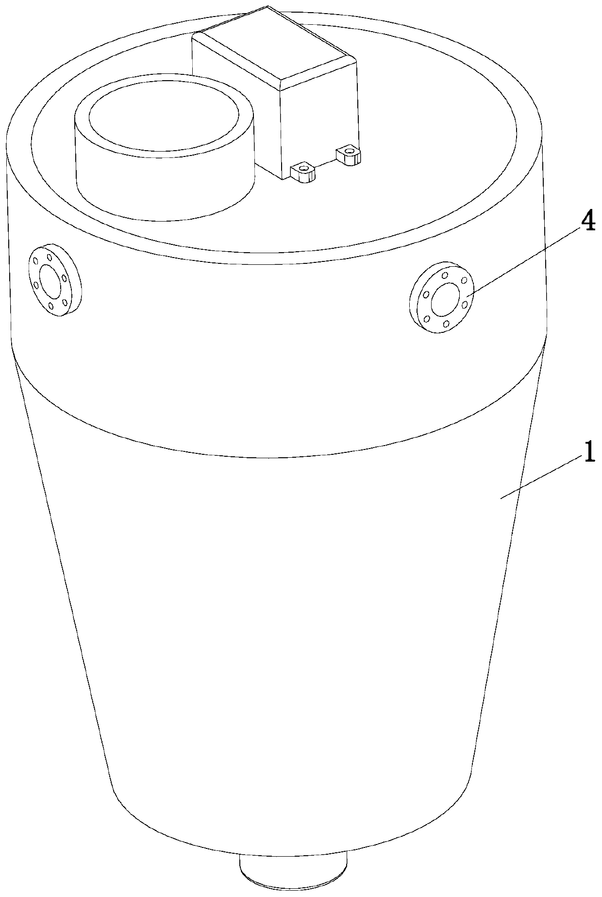
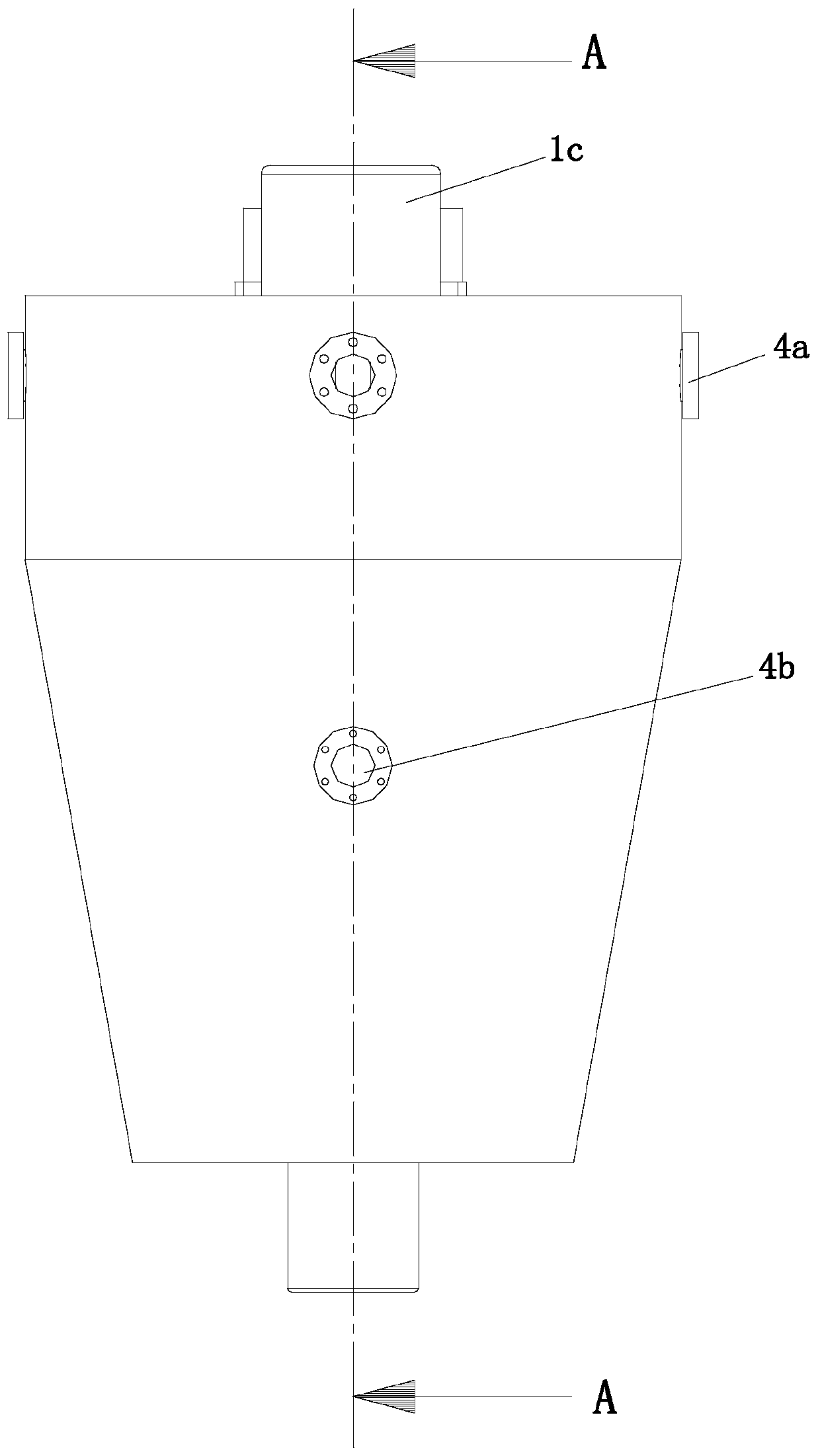
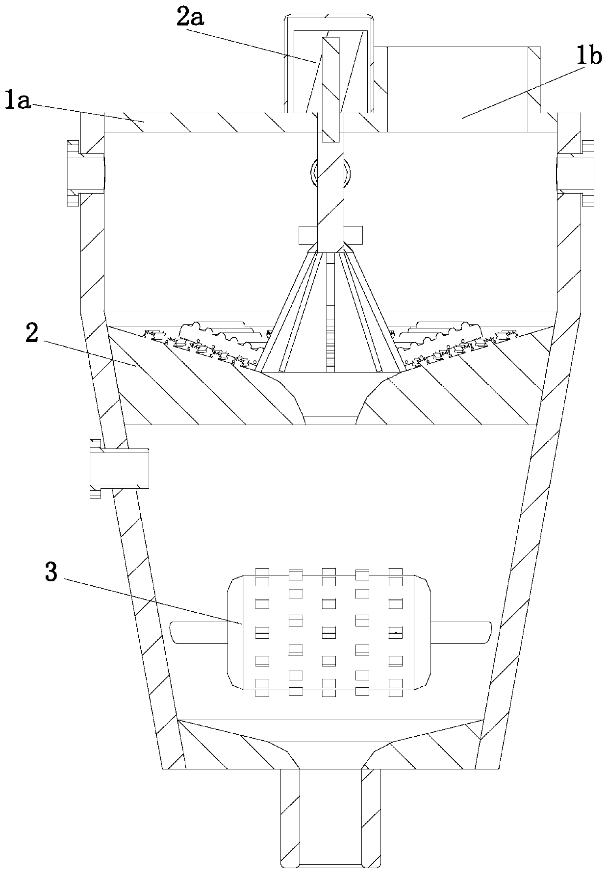
[0034] refer to Figure 1 to Figure 12 A food waste treatment device shown includes a treatment box 1, a primary crushing mechanism 2, a secondary crushing mechanism 3, and an inflow flushing mechanism 4. The treatment box 1 is an inverted conical structure and is a hollow structure. The processing box 1 includes an openable upper cover plate 1a, and the upper cover plate 1a is provided with a feed port 1b for the food waste to be processed to enter the processing box 1, and the primary crushing mechanism 2 and the secondary crushing mechanism 3 It is sequentially arranged in the treatment box 1 along the flow direction of the food waste, the water inlet flushing mechanism 4 is arranged on the outer peripheral wall of the treatment box 1 and communicates with the inside of the treatment box 1, and the primary crushi...


PUM


Abstract

The invention relates to the technical field of garbage treatment and especially relates to a kitchen waste treatment device which includes a treatment box, a primary crushing mechanism, a secondary crushing mechanism and a water feeding and flushing mechanism. The treatment box has an inverted conical hollow structure and includes an openable upper cover plate on which a material inlet is arranged. The water feeding and flushing mechanism is arranged on the outer periphery wall of the treatment box and is communicated with interior of the treatment box. The primary crushing mechanism includesa driving unit, a rotational unit and a first crushing unit, wherein a first through hole is disposed in the center of the rotational unit. The secondary crushing mechanism includes two second crushing units which are disposed symmetrically and can be engaged with each other. A flow guiding unit is arranged right under the second crushing units. A discharge pipe is arranged on the bottom of the flow guiding unit. Through two steps of crushing, the kitchen waste can reach discharge standard, so that the device can satisfy demands on crushing treatment of the kitchen waste.

Description

technical field [0001] The invention relates to the technical field of garbage treatment, in particular to a kitchen garbage treatment device. Background technique [0002] With the acceleration of urbanization, people's living standards have improved significantly, and the catering service industry has developed rapidly. However, due to the inherent living and eating habits and some waste phenomena in our country, a large amount of kitchen waste is generated. Food waste disposers, especially those designed for household use, are usually installed under the sink and connected to the sewer of the sink. Directly connected, for shredding larger food waste so that it can drain with the water from the sink drain. [0003] In order to solve the above problems, the patent application No. 200810141668.2 discloses a food waste processing device, including a shredding chamber, the shredding chamber includes a feed inlet and a shredded object outlet, and a shredding mechanism is insta...

Claims


Application Information

Patent Timeline
IPC IPC(8): E03C1/266
CPCE03C1/2665
Inventor 李斌
Owner 工大环境股份有限公司
Why Eureka
Try Eureka